SBAA463A january 2021 – april 2023 TMAG5170 , TMAG5170-Q1 , TMAG5170D-Q1 , TMAG5173-Q1 , TMAG5273
4.2.1 Sensitivity Gain Correction
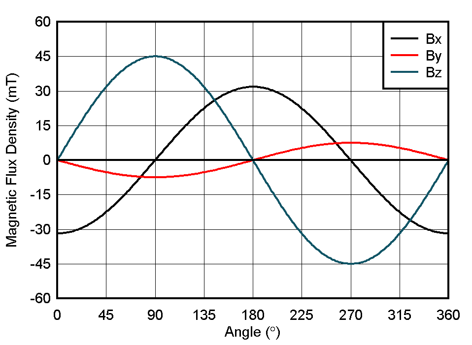
Efforts with simulation software helped find an off-axis placement which resulted with a peak input in the Z-direction of approximately 45 mT. The same placement results in a peak magnitude of about 32 mT in the X-direction.
 Figure 4-5 Simulated Off-Axis
Configuration
Figure 4-5 Simulated Off-Axis
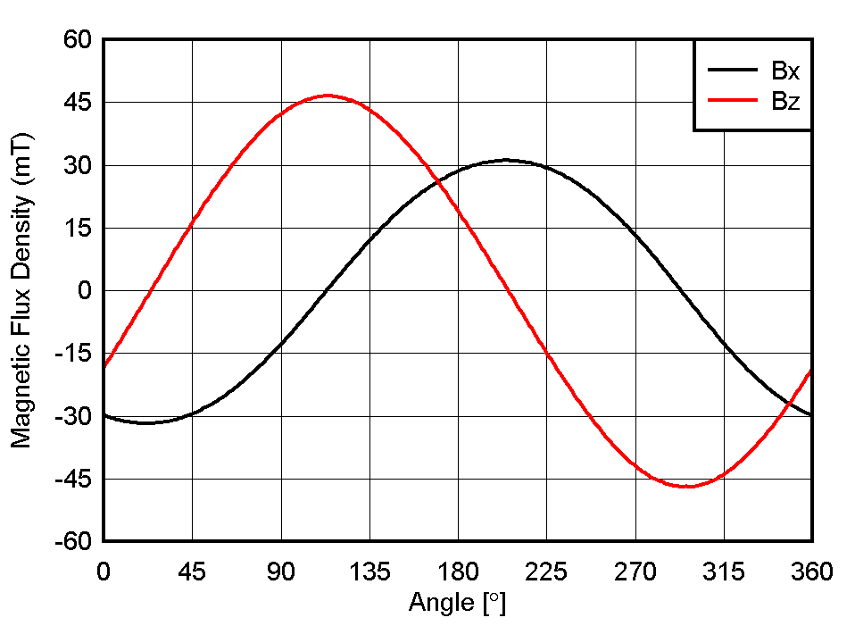
ConfigurationThis configuration was then matched in a physical setup and the outputs of a single rotation were captured. Here we see fairly close behavior between the X and Z components in the simulation and the captured results.
 Figure 4-6 Initial Off-Axis Measured
Data
Figure 4-6 Initial Off-Axis Measured
DataTo properly configure TMAG5170 for angular measurements it was necessary to attenuate the Z component to match the X component following the procedure detailed in Sensor Calibration. Based on measurements of peak input values, a scaling factor of 67.3% was determined to be required to match peak amplitudes.