SBAA546 March 2022 AMC23C12 , AMC23C12-Q1
Design Goals
| Nominal Current | Overcurrent Level | High-Side Supply | Low-Side Supply | Transient Response Time |
|---|---|---|---|---|
| 50 A | 55 A | 3 V–27 V | 2.7 V–5.5 V | ≤ 1000 ns |
Design Description
This high-speed, isolated bidirectional overcurrent detection circuit is implemented with the AMC23C12. The AMC23C12 features an isolated window comparator and an adjustable threshold level via a fixed internal precision current source and user-selectable resistor. This circuit is designed for fast detection of overcurrent situations allowing the controller to disable pulse width modulation (PWM) control of high-speed switches used in motor control, traction inverter, and other industrial control systems.
Design Notes
- To minimize errors, choose a precision shunt resistor (R1) and the threshold-setting resistor (R2).
- The AMC23C12 is powered from the gate-drive supply or high-side auxiliary source up to 27 V.
- Select the shunt resistor and threshold-setting resistors to match the nominal current and overcurrent limits using the window comparator mode of operation.
Design Steps
- Determine the size of the shunt resistor based on
the nominal current level. The shunt resistor is sized to allow 50 mV at the
input pin.
- Determine the value of R2 based on the desired
current trip level using the internal 100-µA source and the desired trip level
of 55 A with a 1-mΩ shunt for 55 mV at the input to the window
comparator.
- Using the Analog Engineers Calculator, the closest E96 resister value to 550 Ω is 549 Ω.
- Optional - select a 27-V Zener diode to protect the AMC23C12 from voltages greater than the recommended operating supply voltage.
Design Simulations
The following images are SPICE simulations of the overcurrent protection circuit. The simulations show the time until the edges trigger which is approximately 360 ns.
Design Results
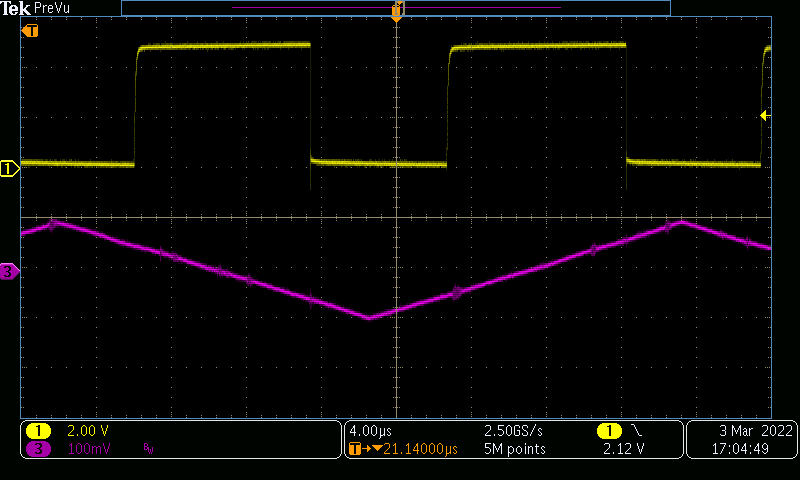
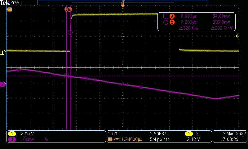
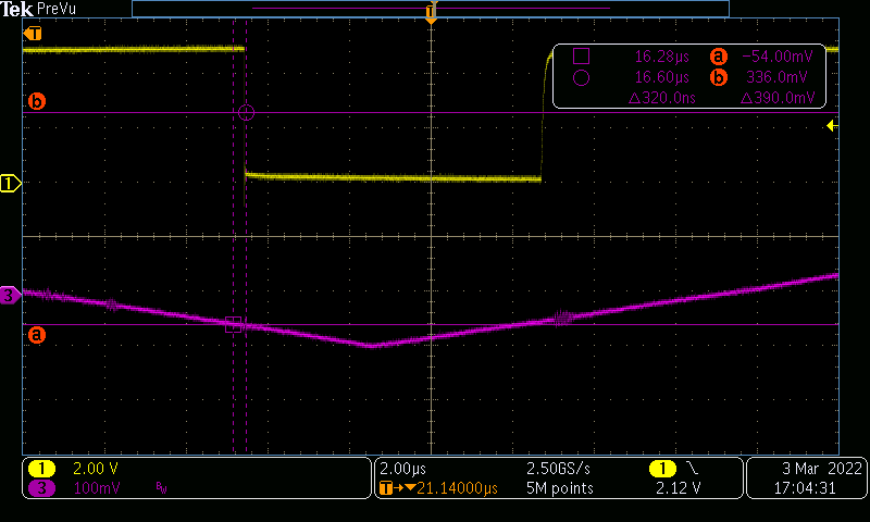
The following images are the waveform captures of the physical circuit. Overcurrent Protection Circuit Waveform shows the output on line 1 with relation to input on line 3. Overcurrent Protection Circuit Waveform - Rising shows the rising edge of the output line 1 and the time delay from the triggered current to the output. Overcurrent Protection Circuit Waveform - Falling shows the falling edge of the output line 1 and the time delay from the triggered current to the output.
 Overcurrent Protection Circuit Waveform
 Overcurrent Protection Circuit Waveform - Rising
 Overcurrent Protection Circuit Waveform - Falling
Design Featured Devices
| Device | Key Features | Device Link |
|---|---|---|
|
AMC23C12 |
|
Device: AMC23C12 Similar Devices: Isolated amplifiers |
Design References
See Analog Engineer's Circuit Cookbooks for TI's comprehensive circuit library.
Texas Instruments, AMC23C12 Fast Response, Reinforced Isolated Window Comparator With Adjustable Threshold and Latch Function data sheet