SBAU391 December 2021 TMAG5328 , TMAG5328
1 Introduction
The linear head-on travel attachment has two portions, each of which have different STL 3D print files. Nylon was selected for the material of the two portions of the attachment because it will not interfere with the magnetic field generated by the magnet and also bonds well when glued to the utilized magnet.
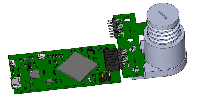
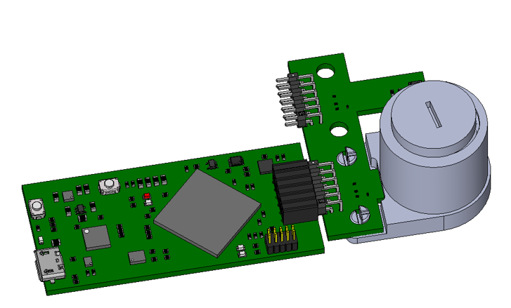
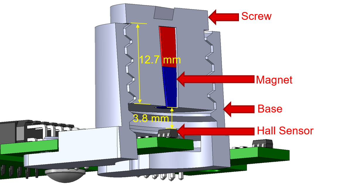
The first portion of the attachment is the screw, which has a thread with 3-mm pitch. The bottom base of the screw has an opening where a N52 grade cylindrical magnet is placed, thereby causing a magnetic field in the Z direction that can be sensed by the Hall position sensor. When the screw is fully unfastened at the top of the base (see Figure 1-1), the distance from the attachment to the top of the Hall position sensor’s package is approximately 16.5 mm. The threading on the screw has a length of 12.7 mm. As a result, the linear displacement from when the screw is fully unscrewed at the top of the base to when it is fully screwed into the base is approximately 12.7 mm (see Figure 1-2). In addition, the distance from the top of the Hall sensor package to the magnet is approximately 3.8 mm when the screw is fully fastened. Figure 1-3 shows a cross-section view of the attachment when the screw is fully fastened into the base.
 Figure 1-1 Linear Head-On Travel Attachment
With Screw Fully Unfastened From Base
 Figure 1-2 Linear Head-On Travel Attachment
With Screw Fully Fastened into Base
 Figure 1-3 Cross-section of Linear Head-On
Travel Attachment With Screw Fully Fastened into Base
Figure 1-3 Cross-section of Linear Head-On
Travel Attachment With Screw Fully Fastened into BaseThe second portion of the attachment is the base. The screw part of the attachment gets fastened into the top portion of the base, which is directly above the Hall position sensor. The screw can be rotated by hand or by using a flat head screwdriver on the slot at the top of the screw. Turning the screw clockwise when it is within the base causes the magnet to decrease its distance with respect to the Hall sensor, thereby increasing the magnetic flux density sensed by the Hall position sensor. To decrease the magnetic flux density seen by the sensor, the screw should be rotated counterclockwise to increase the distance from the Hall position sensor to the magnet embedded within the screw. Using the sensed magnetic flux density and information on the characteristics of the magnet, the linear distance from the magnet to Hall sensor can be calculated. Refer to the Head-on Linear Displacement application brief for more information.