SBAU392A July 2022 – January 2023 AFE7950 , TRF1208
- TRF1208-AFE7950-EVM Evaluation Module User's Guide
- Trademarks
- 1EVM Overview
- 2Hardware Setup (TSW14J56 Used as an Example)
- 3Latte Overview
- 4TRF1208-AFE7950-EVM Automatic Configuration
- 5Status Check and Troubleshooting Guidelines
- 6TRF1208-AFE7950-EVM Manual Configuration
- 7Setup the TSW14J5x With the HSDC Pro
- 8Revision History
4.3 RXADC and FBADC Evaluation
- Before starting the RXADC and FBADC performance
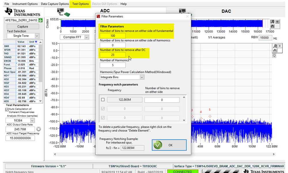
capture, the test option of the HSDC PRO must be setup. Go to Test
Options to enter the Filter Parameters menu. By default, there
are 25 bins to remove on either side of fundamental and 25 bins near DC to
remove. As shown in Figure 4-9, change the number of bins to remove on either side of fundamental to 100
bins.
- With 245.76 MSPS of data rate for RXADC at 16384 sample points, this removes 1.5 MHz of bins on either side of the fundamental.
- With 491.52 MSPS of data rate for FBADC at 16384 sample points, this removes 3.0 MHz of bins on either side of the fundamental.
- The number of bins to be removed is a standard recommendation from TI to remove the effect of the ADC sampling clock in-band phase noise from affecting the broadband noise used to calculate the SNR through the FFT engine. The number of bins must be adjusted based on the end-application standard.
 Figure 4-9 HSDC PRO ADC
Performance FFT Binning Configuration
 - Connect the RF signal generator output to J3 (RXA_IN), J1 (RXB_IN), and J4 (RXC_IN) to capture the RF input to the ADC. On the High-Speed Data Converter Pro, press the Capture button to capture the ADC data.
- Feed in a tone of 10 MHz offset from the channel frequency. For example, feed 2310 MHz to RXA_IN, 5010 MHz to RXB_IN, and 6010 MHz to FB1_IN. Set the signal level to get about -4 dBFS at the ADC output. Since the gain is different for various channels, the signal generator's output levels will be different.
- RXA_IN is Channel 1 and 2 in FFT Channel Selection
- RXB_IN is Channel 3 and 4 in FFT Channel Selection
- FB1_IN is Channel 1 and 2 in FFT under FB mode Channel Selection
- Similarly, feed 8010 MHz to RXC_IN and 6010 MHz to FB2_IN. Set the signal level to get about -4 dBFS at ADC output.
- RXC_IN is Channel 5 and 6 in FFT Channel Selection
- FB2_IN is Channel 3 and 4 in FFT under FB mode Channel Selection
- For Feedback ADC, execute the following commands or execute AFE79xx_FB_Capture.py through the F5 key.
###### Configure FB-ADC
####################################################
AFE.TOP.overrideTdd(0,3,0)
hsdcparam.fb.Datarate=sysParams.FadcFb/sysParams.ddcFactorFb[0]*1e6confighsdcpro().fb()