SBAU396 May 2022
4.1 Schematics
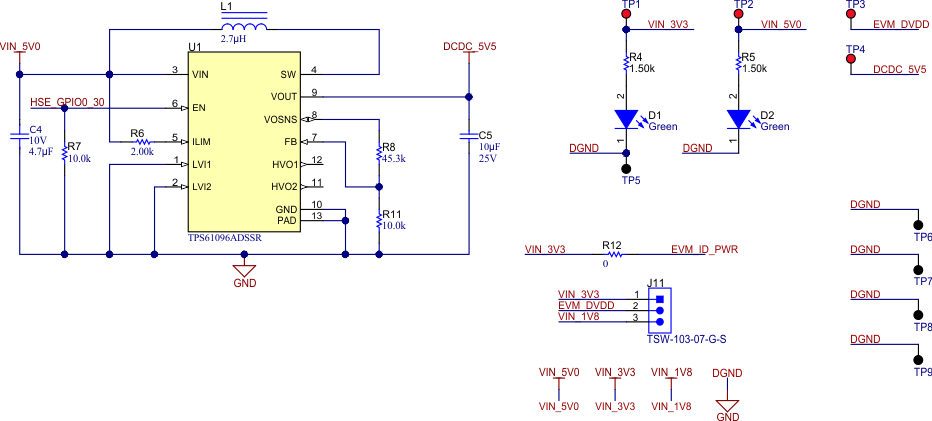
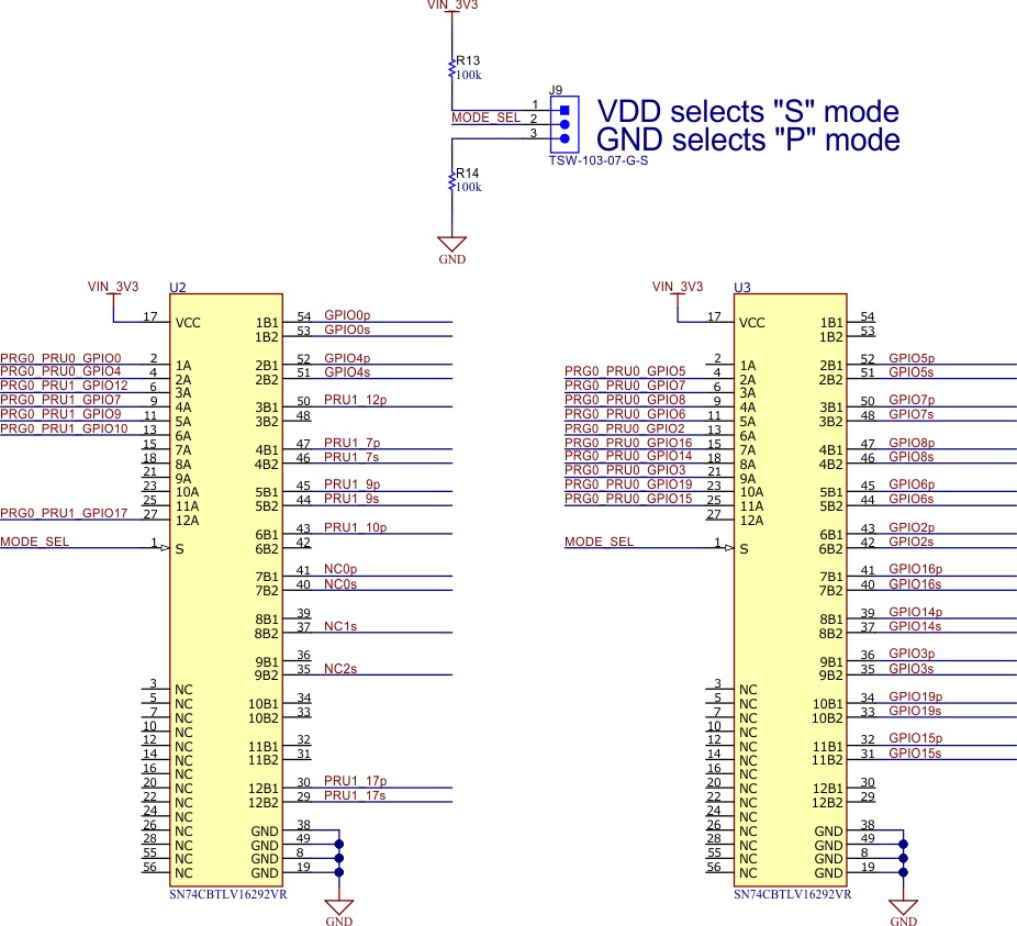
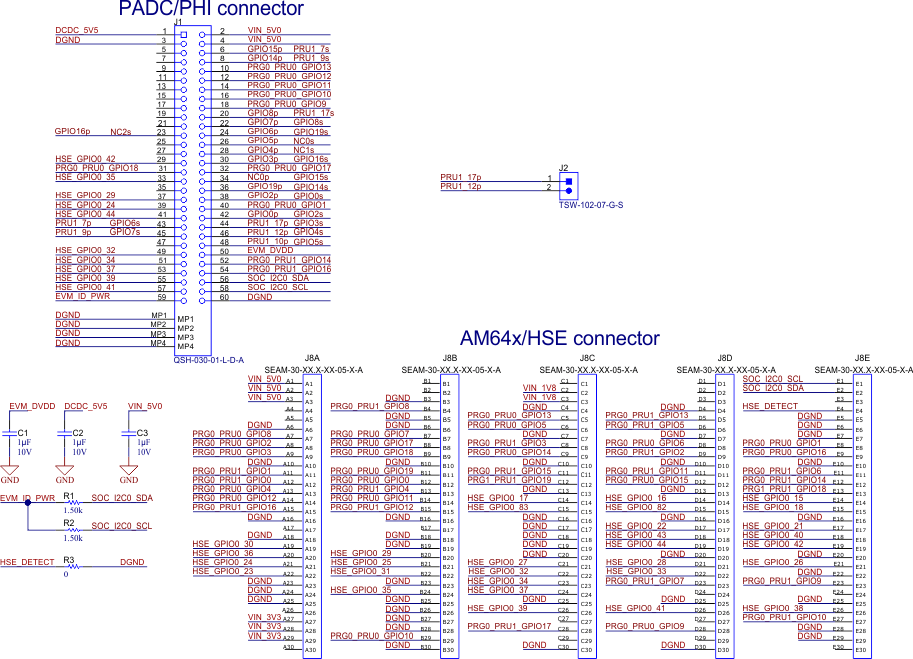
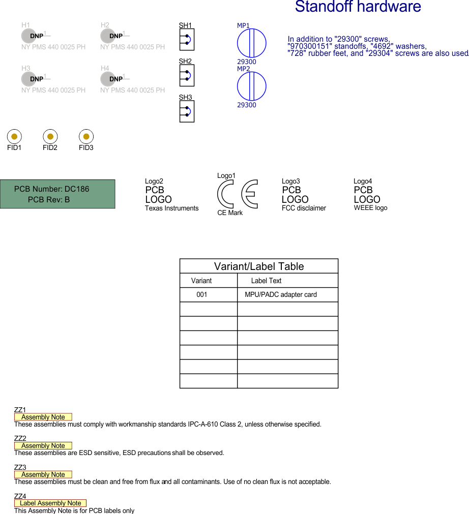
Figure 4-1 to Figure 4-4 illustrate the schematics for the ADC-PHI-PRU-EVM.
 Figure 4-1 ADC-PHI-PRU-EVM Power Schematic Page
 Figure 4-2 ADC-PHI-PRU-EVM MUX Schematic Page
 Figure 4-3 ADC-PHI-PRU-EVM Connectors Schematic Page
 Figure 4-4 ADC-PHI-PRU-EVM Hardware Schematic Page