SBAU396 May 2022
3.2 MUX Circuitry
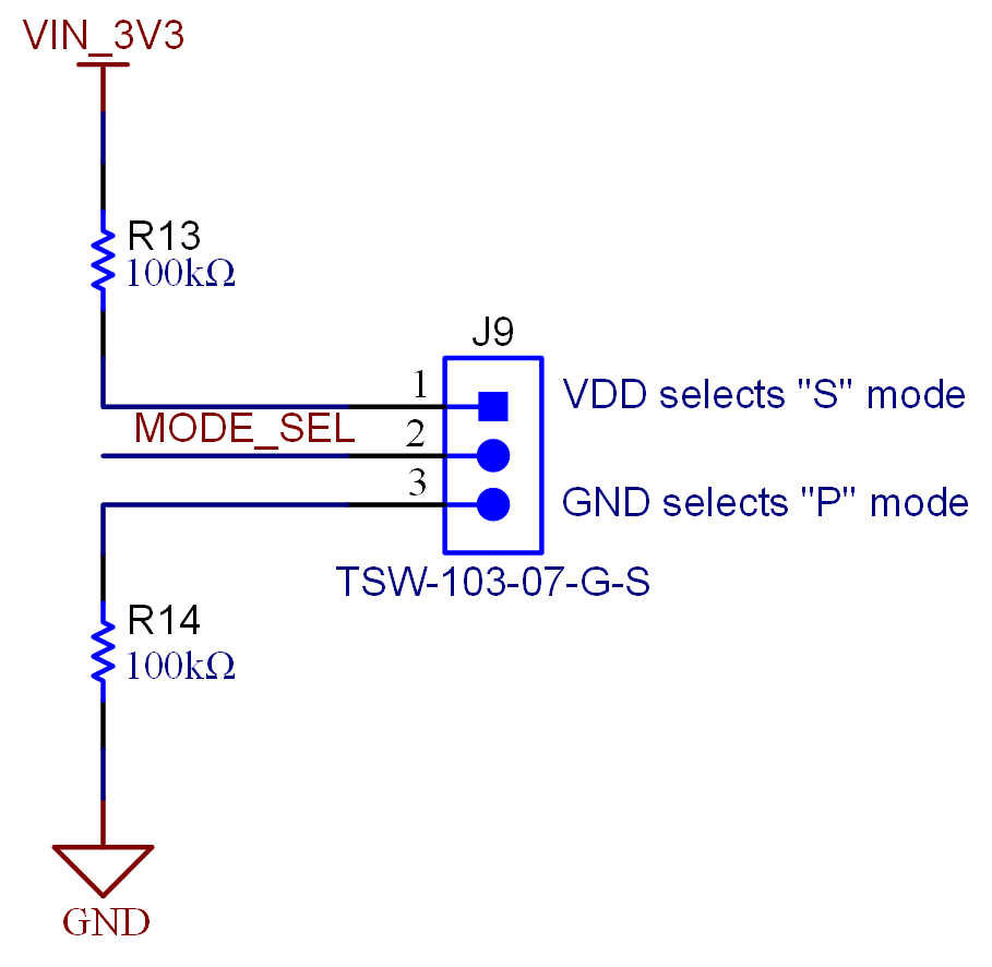
PA007-based precision ADC EVMs share several pins between the parallel and serial modes of operation depending on how the controller card is configured by the EVM GUI. There are two SN74CBTLV16292VR digital multiplexer (MUX) devices on the ADC-PHI-PRU-EVM that route the proper signals from the AM64x and AM243x EVMs (TMDS64GPEVM and TMDS243GPEVM) to communicate with either the parallel or serial precision ADC EVMs. Figure 3-4 shows how the J9 jumper sets the voltage level on the MUX device selection pins that route the A side PRU signals from the HSE connector to either the B1 (parallel) or B2 (serial) connections on the B side. The signal routing to the MUX devices for both parallel and serial communication modes is provided in the full schematics of Section 4.1.
 Figure 3-4 J9 Selects Between Serial (S) and Parallel (P)
Communication With the ADC