SBOA447 November 2020 ALM2402-Q1 , ALM2402F-Q1 , ALM2403-Q1
3 ALM2402F-Q1 and ALM2403-Q1 Overvoltage Protection for Low Battery Voltages
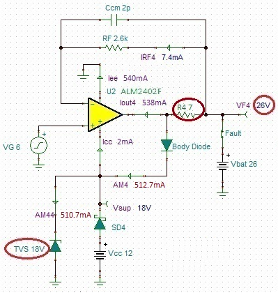
Since the absolute maximum rated supply voltage for ALM2402F-Q1 is 18 V, shorting the output above said voltage requires extra circuitry to prevent EOS damage. To this end, Vsup must be protected by Transient Voltage Suppressor (TVS), a fast activated Zener diode with a breakdown voltage of 18 V or lower, from being pulled close to Vbat through the body diode since this would exceed its maximum rated supply voltage (see Figure 3-1). Additionally, the current through the body diode must be limited to a short-circuit level by adding R4 series resistor, which under short to 26 V fault condition results in over 7 V drop across its 7Ω power resistor (total current of ~1.05A)
 Figure 3-1 ALM2402F-Q1 26V Battery Fault
Protection
Figure 3-1 ALM2402F-Q1 26V Battery Fault
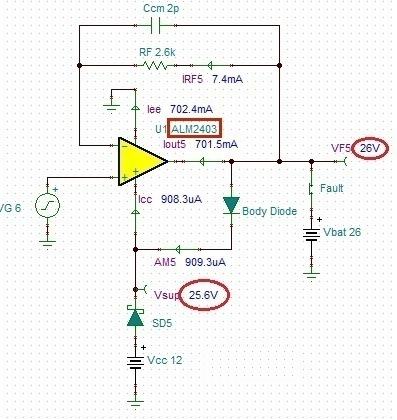
ProtectionHowever, there is a simpler solution to the above problem by using another part - ALM2403-Q1. Because of its higher absolute maximum rated supply voltage, it eliminates the need for extra protection up to 26 V - see Figure 3-2. As was the case with ALM2402F-Q1 shown in Figure 2-2, all that is required here is a blocking diode, SD5, which allows Vsup to be pulled to 25.6 V with no damage.
 Figure 3-2 ALM2403-Q1 26V Battery Fault
Protection
Figure 3-2 ALM2403-Q1 26V Battery Fault
ProtectionNevertheless, as was the case with Vbat above 18 V in case of ALM2402F-Q1, shorting ALM2403-Q1 output above 26 V will similarly require a transient voltage suppressor (TVS) to clamp Vsup at 26 V (or lower). Also, a series output power resistor has to be added to limit the current through internal structures. Therefore, any protection against short to battery or other fault condition must not only protect against over-voltage at the supply pin, Vsup, but also assure that the resulting current through internal and/or external protection structures, does not exceed maximum rated limit specified in the respective product data sheets.
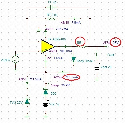
Therefore, for short to battery condition just above 26 V, the simplest way to limit the current through body diode is to include a small resistor inside the feedback loop in series with the ALM2403-Q1 output. For example, under short to 28 V Vbat condition, Isc current (701mA) is being sunk by the amplifier output and adding just 1Ω power resistor, R5, between Vbat and output pin results in safe Vsup of 25.9 V. R5 also limits the body diode current to a safe 713.1mA, thus fully protects ALM2403-Q1 from any damage – see Figure 3-3.
 Figure 3-3 ALM2403-Q1 28V Battery
Protection
Figure 3-3 ALM2403-Q1 28V Battery
ProtectionThis approach works well for battery voltages up to few volts above the part’s absolute maximum rated supply voltage but requires much higher value series output power resistor for higher Vbat that negatively affects the output voltage swing from the rails, and lowers power efficiency, under normal operating conditions. For example, in order to prevent over-current damage to the part under short to a 48 V battery, one would need to add around 20Ω resistor in series with ALM2403-Q1 output. However, under normal linear conditions, with +/-200mA peak output current, this would lower the output voltage swing to each rail by additional +/-4V (total of 8 V), requiring a significant increase in the minimum supply voltage. This in turn would results in much lower power efficiency of the solution and thus may not be a viable option.
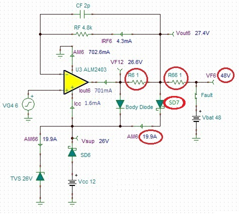
Therefore, in order to protect ALM2403-Q1 under short to high voltage (48 V) Vbat condition, it may be necessary to add an external Schottky diode, SD7, in parallel with the body diode and capable of carrying a very high current – see Figure 3-4. Under such scenario, in order to limit the current through Schottky diode to 20A (or less) this would require adding R66 1Ω power resistor between Vbat and the Schottky diode. Even though for a given current level the forward bias voltage of Schottky diode is much lower than that of the body diode (thus much more of the current would flow through external Schottky and not the body diode), under high current flow of 20A, its forward bias voltage may be 1 V or higher. Therefore, in order to limit the current through the body diode to a safe operating level, it may also be necessary to add another 1Ω series resistor, R6, between SD7 and the amplifier’s output, VF12 – see Figure 3-4.
 Figure 3-4 ALM2403-Q1 48V Battery
Protection