SBOU236A February 2020 – March 2021 ALM2403-Q1
3 Jumper Settings
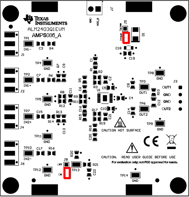
Figure 3-1 details the default jumper settings of the ALM2403Q1EVM. Table 3-1 explains the configuration for these jumpers.
 Figure 3-1 ALM2403Q1EVM Default Jumper Settings
Table 3-1 Default Jumper Configuration
| Jumper | Function | Default Position | Description |
|---|---|---|---|
| J5 | VCC_S reverse polarity protection | Shunt 2-3 | Shunt 2-3: Schottky diode blocks VCC-S supply reverse current Shunt 1-2 bypasses VCC_S Schottky diode protection |
| J8 | SH_DN / OTF | Shunt 2-3 | Overtemperature flag or shutdown: Shunt 2-3 turns on amplifiers; pin works as overtemperature flag Shunt 1-2 shuts down amplifiers |