SLAU628 August 2020 DRV5825P
1 Hardware Overview
The DRV5825P showcases the latest TI digital input Class-D closed-loop amplifier for Piezo applications. The DRV5825P is a digital input Class-D audio amplifier with Smart Piezo Driver Algorithm.
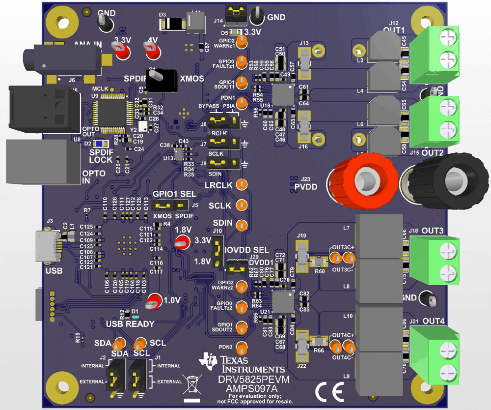
 Figure 1-1 DRV5825PEVM (Top Side)
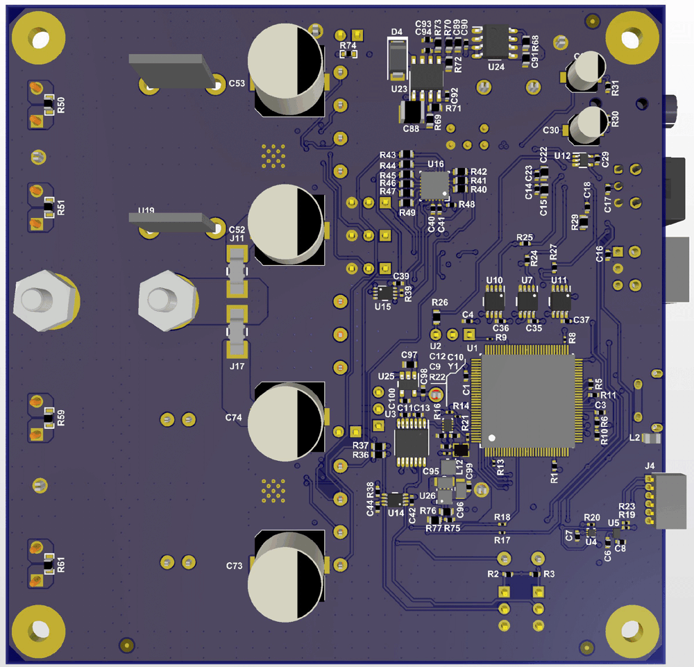
 Figure 1-2 DRV5825PEVM (Bottom Side)
Features
The EVM has the following features:
- Two DRV5825P devices: 2.0 stereo, 1.0 mono, 2.1 and 2.2 capable
- Operates in BTL and PBTL
- Flexible audio source input (USB, S/PDIF, PSIA, and analog)
- Demonstration, evaluation and development via the PPC3™ application
Functions
The DRV5825PEVM has several audio source options. The digital audio data input is selectable from USB audio, optical S/PDIF, and PSIA (external I2S). There is also an analog audio input to the DRV5825PEVM through 3-mm audio jack. The DRV5825PEVM also functions as an optical output source (labeled on the board as OPTO OUT U6) as Figure 1-1 shows. The output of the DRV5825PEVM can either be configured in BTL or PBTL through the load connections to OUT1 (J12), OUT2 (J15), OUT3 (J18), and OUT4 (J21) shown in Figure 1-1.
Detailed Operations
The DRV5825PEVM has four different optional audio sources:
- If the XMOS is selected manually by toggling the S1 switch, the Windows Media® Player can be used to stream audio. GPIO1 SEL (J5) should be configured to XMOS as Figure 1-1 (board view) or Figure 3-2 (schematic view) show.
- If S/PDIF is selected manually by toggling the S1 switch, an optical S/PDIF source (DVD, audio converter, or AP) can be used to stream audio from the OPTO IN connector (U8). GPIO1 SEL (J5) should be configured for S/PDIF as seen in Figure 1-1 (board view) or Figure 3-2 (schematic view).
- If an external digital audio source, such as a Programmable Serial Interface Adapter (PSIA) from Audio Precision (AP)® is desired, the jumpers on the BYPASS selection of LRCLK (J8), SCLK (J7), and SDIN (J9) may be removed as Figure 1-1 (board view) or Figure 3-3 (schematic view) show. The PSIA inputs may be connected to the PSIA selection with the appropriate ground reference aligned with the ground signal on the board.
- If the audio source is analog, it may input from the 3-mm audio jack as Figure 1-1 (board view) or Figure 3-2 (schematic view) show.
Both 3.3 V and 1.8 V DVDD and IOVDD are supported with the DRV5825PEVM. Jumper (J10) can be used to select accordingly based on the requirement of the digital signals to closely mimic the end equipment of the customer as Figure 1-1 (board view) or Figure 3-3 (schematic view) show. PVDD and DVDD of each device may be removed with the corresponding jumpers in Table 1-1:
| Device | PVDD | DVDD |
|---|---|---|
| U18 (Top - OUT1 and OUT2) | J11 | DVDD2 (J14) |
| U21 (Bottom OUT3 and OUT4) | J17 | DVDD1 (J21) |
The USB connection is also used to provide I2C communications with DRV5825P on the EVM. The EVM provides selection of providing external I2C is the use of the GUI/XMOS is not desired through SDA (J2) and SCL (J1) as seen in Figure 1-1 (board view) or Figure 3-1 (schematic view). The PPC3™ application for this device is used to initialize and operate this EVM.