SLAU780 August   2018


  1.   MSP432E411Y-BGAEVM User's Guide
    1.     Trademarks
    2. 1 Board Overview
    3. 2 Power the MSP432E411Y-BGAEVM
      1. 2.1 Emulator Power
      2. 2.2 External 3.3-V Source Only
      3. 2.3 External 5-V Source Only
      4. 2.4 External 3.3-V and 5-V Source
      5. 2.5 Measure Current Consumption
    4. 3 Header Pinouts and Connections
      1. 3.1 J11 – External Power Connector
      2. 3.2 J6 – Power Rail Header
      3. 3.3 J7 – External Peripheral Interface Header
      4. 3.4 LCD Interface Header
      5. 3.5 J1, J2, J3, J4 – BoosterPack Interface Headers
      6. 3.6 J5 – Additional GPIO Pin Header
    5. 4 Communication Interfaces
      1. 4.1 Ethernet
      2. 4.2 USB-OTG
    6. 5 Programming Interfaces
      1. 5.1 JTAG
      2. 5.2 ETM Trace
      3. 5.3 BSL
    7. 6 Software Development
      1. 6.1 Software Description
      2. 6.2 Source Code
      3. 6.3 Tool Options
    8. 7 Schematics

Measure Current Consumption

To measure current consumption, remove the JP1, JP2, or JP3 jumpers and place an ammeter across the header pins. Connect this jumper when not performing current measurements. Figure 3 shows the location of JP1, JP2, and JP3. Table 1 lists which power rail to measure on each jumper.
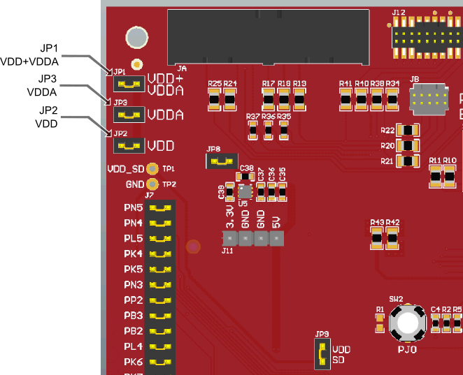
current-measurement-headers.pngFigure 3. Current Measurement Headers

Table 1. Power Measurement Jumpers

Jumper Power Rail Measured
JP1 Combined VDD and VDDA
JP2 VDD
JP3 VDDA