SLAU874 October   2022 TPA3223


  1.   TPA3223 Evaluation Module
    1.     Trademarks
    2. 1.1 Quick Start (BTL MODE)
      1. 1.1.1 Required Hardware
      2. 1.1.2 Connections and Board Configuration (BTL MODE)
      3. 1.1.3 Power-Up
    3. 1.2 Setup By Mode
      1. 1.2.1 BTL MODE (Stereo - 2 Speaker Outputs)
      2. 1.2.2 PBTL MODE (Mono – 1 Speaker Output)
        1. 1.2.2.1 Connections and Board Configuration
        2. 1.2.2.2 Power-Up
    4. 1.3 Hardware Configuration
      1. 1.3.1 Indicator Overview (OTW_CLIP and FAULT)
      2. 1.3.2 PWM Frequency Adjust
      3. 1.3.3 Modulation Modes (AD Mode and HEAD Mode)
      4. 1.3.4 Output Mode Selection
      5. 1.3.5 Audio Front End
      6. 1.3.6 EVM Power Tree
        1. 1.3.6.1 TPA3223 Supplies
        2. 1.3.6.2 TPA3223EVM Power Options
          1. 1.3.6.2.1 PVDD Only (12 V to 45 V)
          2. 1.3.6.2.2 PVDD (12 V to 45 V) and One Non-5-V Supply
          3. 1.3.6.2.3 PVDD (12 V to 45 V) and 5-V Supply
      7. 1.3.7 LC Response and Overview
      8. 1.3.8 Reset Circuit and POR
      9. 1.3.9 Analog-Input-Board Connector (J28)
    5. 1.4 EVM Design Documents
      1. 1.4.1 TPA3223 Board Layouts
      2. 1.4.2 TPA3223 Board Layouts
      3. 1.4.3 TPA3223EVM Schematics
      4. 1.4.4 TPA3223EVM Bill of Materials
  2.   Trademarks
  3. 1Quick Start (BTL MODE)
    1. 1.1 Required Hardware
    2. 1.2 Connections and Board Configuration (BTL MODE)
    3. 1.3 Power-Up
  4. 2Setup By Mode
    1. 2.1 BTL MODE (Stereo - 2 Speaker Outputs)
    2. 2.2 PBTL MODE (Mono – 1 Speaker Output)
      1. 2.2.1 Connections and Board Configuration
      2. 2.2.2 Power-Up
  5. 3Hardware Configuration
    1. 3.1 Indicator Overview (OTW_CLIP and FAULT)
    2. 3.2 PWM Frequency Adjust
    3. 3.3 Modulation Modes (AD Mode and HEAD Mode)
    4. 3.4 Output Mode Selection
    5. 3.5 Audio Front End
    6. 3.6 EVM Power Tree
      1. 3.6.1 TPA3223 Supplies
      2. 3.6.2 TPA3223EVM Power Options
        1. 3.6.2.1 PVDD Only (12 V to 45 V)
        2. 3.6.2.2 PVDD (12 V to 45 V) and One Non-5-V Supply
        3. 3.6.2.3 PVDD (12 V to 45 V) and 5-V Supply
    7. 3.7 LC Response and Overview
    8. 3.8 Reset Circuit and POR
    9. 3.9 Analog-Input-Board Connector (J28)
  6. 4EVM Design Documents
    1. 4.1 TPA3223 Board Layouts
    2. 4.2 TPA3223 Board Layouts
    3. 4.3 TPA3223EVM Schematics
    4. 4.4 TPA3223EVM Bill of Materials

TPA3223EVM Schematics

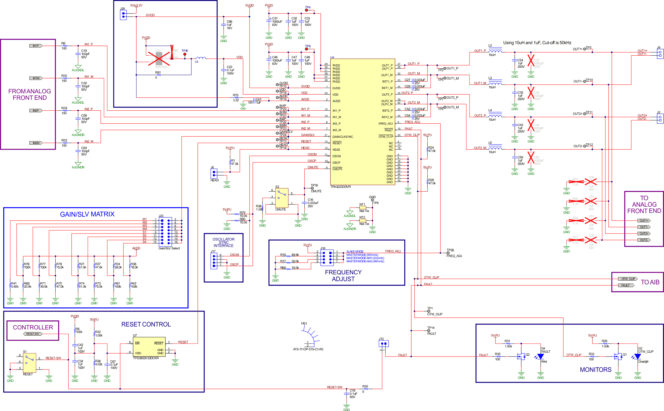
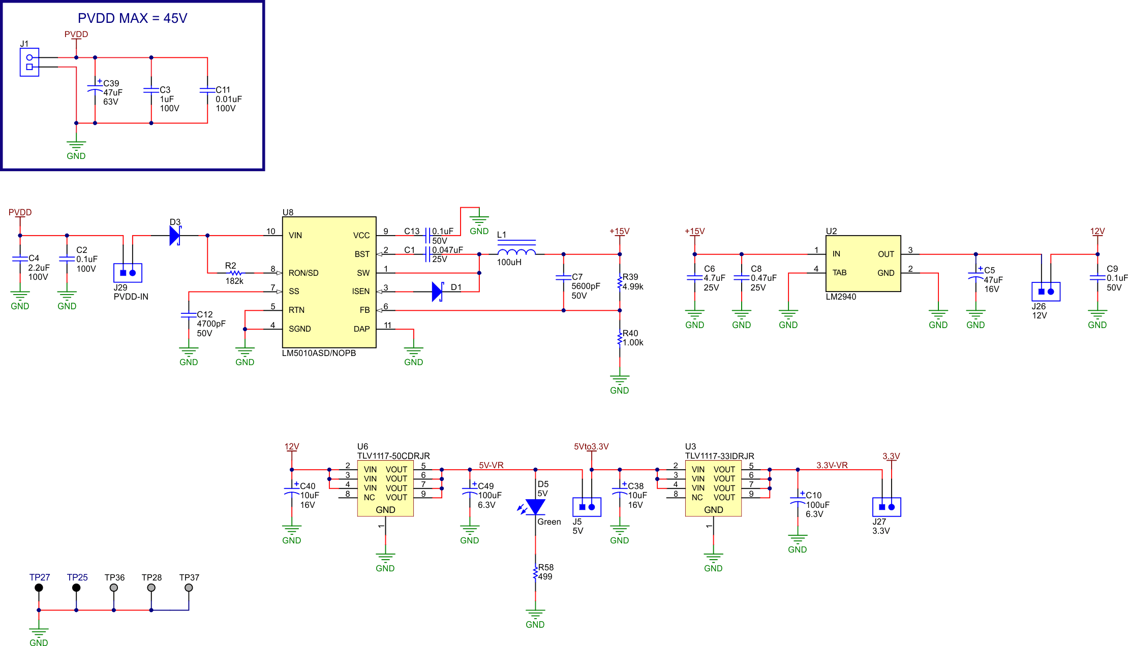
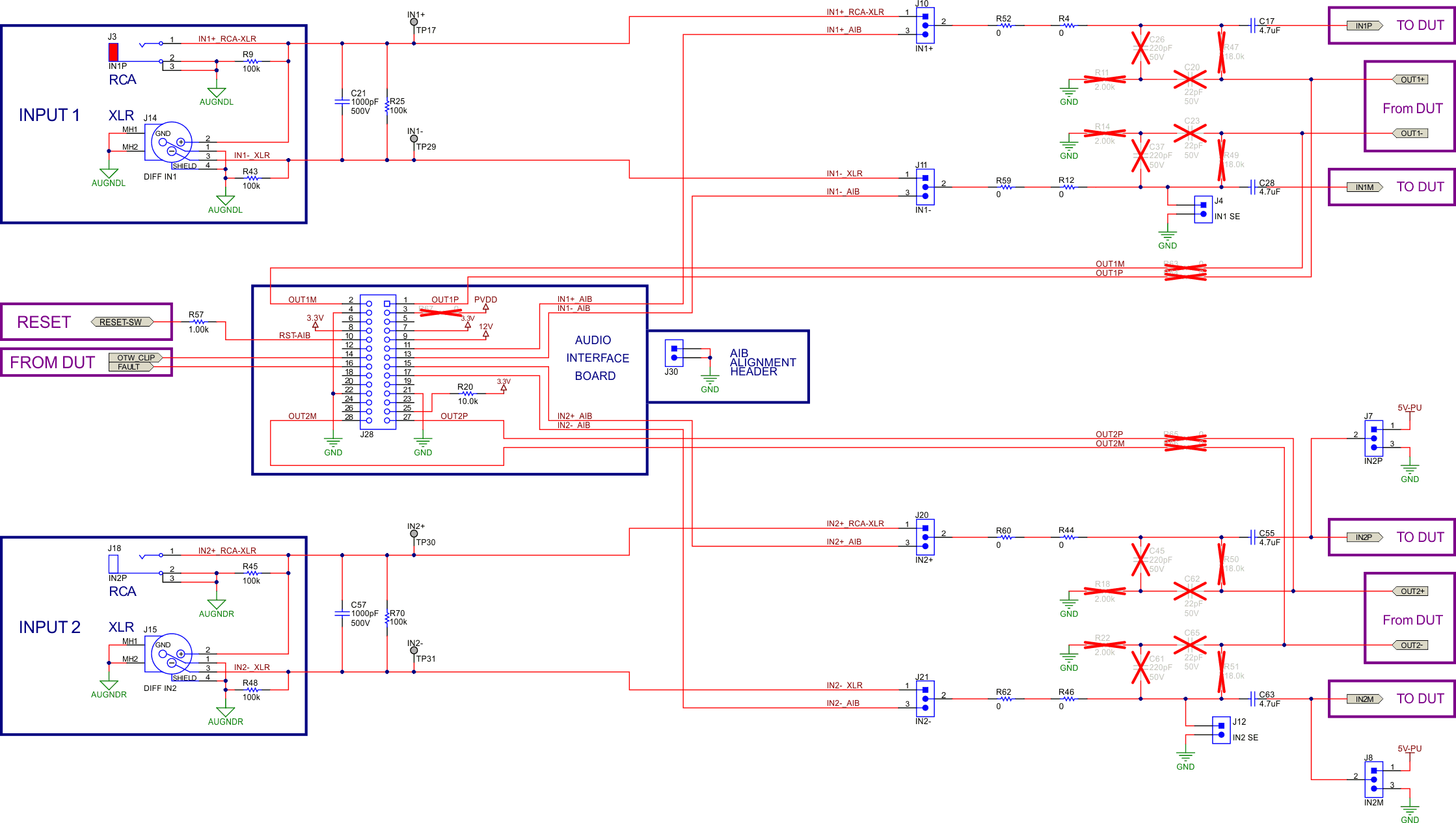
Figure 4-18 through Figure 4-20 illustrate the TPA3223 EVM schematics.

Note: TPA3223EVM with the AMPS174A marking have 5V-PU connected to 5V(5Vto3.3V) supply net externally via wire. This is required for A revision boards for proper operation.
GUID-20220912-SS0I-59D8-TRTV-38WQJL1PJQZW-low.gif Figure 4-18 TPA3223EVM Schematic 1
GUID-20220912-SS0I-X2Z5-LTGN-BDJFG2CGFDPH-low.gif Figure 4-19 TPA3223EVM Schematic 2
GUID-20220912-SS0I-049Z-SFNW-QD2CSGG9BB8Z-low.gif Figure 4-20 TPA3223EVM Schematic 3