SLIA096 January 2022 DRV5021 , DRV5021-Q1 , DRV5023 , DRV5023-Q1 , DRV5032 , DRV5033 , DRV5033-Q1 , TMAG5123 , TMAG5123-Q1 , TMAG5124 , TMAG5124-Q1 , TMAG5131-Q1 , TMAG5231 , TMAG5328
2.8.2 Roll, Yaw, and Pitch
Roll, yaw, and pitch correspond to how a mechanical body may be rotated away from its intended variation. In our rocker switch system, there are multiple bodies that could have some roll, yaw, and pitch. These bodies include the Hall-effect switch, the rocker base, the rocker axle, the rocker, and the magnet. Figure 2-26 illustrates roll, yaw, pitch for the magnet.
Post analysis revealed that some magnets embedded in the rocker switches were not flush with the bottom of the magnet cavity. This led to some roll in the magnet orientation. Since the slots in the PCB for the rocker switch were hand drilled, those slots had tolerance that led to rocker switch yaw. Lastly as some slots were a little too large, the rocker switch had some wiggle room that resulted in some magnet pitch as well as additional offset.
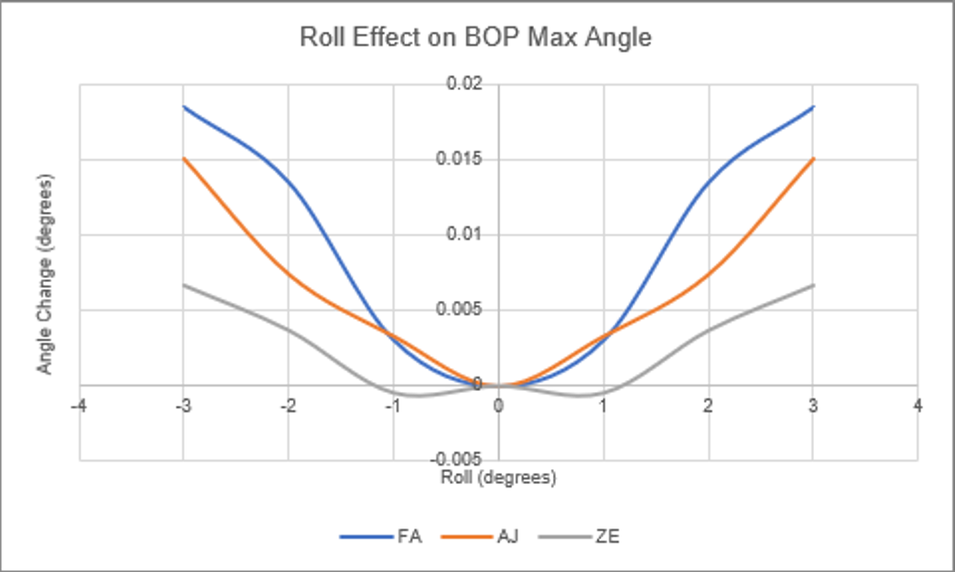
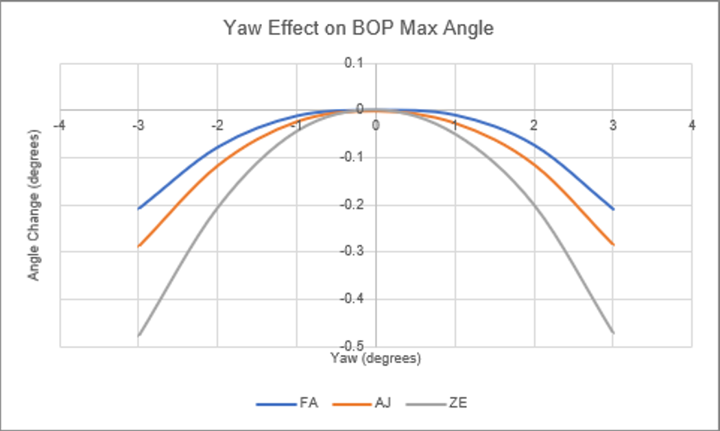
The influence of magnet roll and rocker base yaw are simulated below. Tighter manufacturing tolerance with respect to the rocker switch magnet cavity and PCB slots are expected to minimize this respective error.
Figure 2-27 illustrates the impact of roll on BOP maximum angle while Figure 2-28 illustrates the impact of yaw on BOP maximum angle.
 Figure 2-27 Roll Effect on BOP Maximum Angle
Figure 2-28 Yaw Effect on BOP Maximum Angle