SLIA096 January 2022 DRV5021 , DRV5021-Q1 , DRV5023 , DRV5023-Q1 , DRV5032 , DRV5033 , DRV5033-Q1 , TMAG5123 , TMAG5123-Q1 , TMAG5124 , TMAG5124-Q1 , TMAG5131-Q1 , TMAG5231 , TMAG5328
2.2 Magnetic Implementation
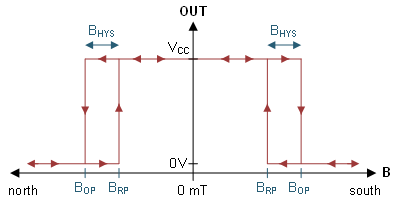
Upon choosing a style or mechanical implementation of the switch, consider how to transduce the mechanical stimulus into an electrical signal utilized by the system. Hall-effect sensors, especially Hall-effect switches, are a great option. Figure 2-3 illustrates the basic operation of an omnipolar Hall-effect switch. The image shows that a Hall-Effect switch has binary states of high and low, with the typical Hall-effect switch asserting low when the magnitude of the sensed magnetic field exceeds the BOP threshold and the Hall-effect switch re-asserting high when the magnitude falls below the BRP threshold. We can generalize that a magnet will trigger the Hall-effect switch low when it approaches and then trigger the Hall-effect switch high when it departs. However, the distance at which these triggers occur depends largely on the magnet specifications, the Hall-effect switch specifications, switch orientation, magnet orientation, and the displacement distance between the magnet and Hall-effect switch.
 Figure 2-3 Omnipolar Behavior
As noted, device orientation does matter. While there are 3D Hall-effect sensors like the TMAG5170 and TMAG5273, Hall-effect switches do not sense magnetic fields in all directions and not all Hall-effect switches sense magnetic fields in the same direction. Figure 2-4 shows some examples of how a Hall-effect switch senses a magnetic field. In the left example is a typical surface mount SOT-23 Hall-effect sensor that senses in the z-direction like the TMAG5231. In the middle is another SOT-23 like the TMAG5123 that senses magnetic fields parallel to the package in the x or y direction. Lastly on the right is a typical through-hole TO-92 that senses in the x or y direction like the DRV5032AJLPG.
To better understand how relative magnet orientation and displacement affect sensor detection, examine the B-field of the block magnet in Figure 2-5. From this figure a few useful high-level concepts are derived. Points 1 and 2 correspond to the exit and entry points for the magnetic field radiating from the surface of the magnet. As the field enters from all 360° in the xy plane, these points see a strong field magnitude, purely oriented in the z-axis. As we move away from the points we see that the magnetic field begins to wrap around traveling from the North pole to the South pole. Consequently, as the direction of the field changes, we can expect that only a fraction of the field will be oriented in the z-direction and furthermore as the field lines do not converge at these other locations, the total field will be less than what is at points 1 and 2. Additionally, the longer the path the magnetic flux must travel from North to South, the greater the reluctance resisting the radiation of magnetic flux and the weaker the magnetic field (signified by the thinner field lines). With this basic understanding of the field pattern of the magnet and the relative field strength at various locations in space some reasonable assertions can be made on how the magnet and sensor should be oriented within the rocker switch.
Equipped with this basic understanding of Hall-effect sensing direction and the field characteristics of a magnet, various general methods can now be formulated for the end goal. The end goal is to transduce our mechanical action into a system response through the following steps. The mechanical action is transduced into a field change sensed by our Hall-effect switch. Subsequently the Hall-effect switch translates this magnetic signal into an electrical signal. The electrical signal from the output of the Hall-effect then prompts some reaction from an actuator or microprocessor.
One key detail seen in Figure 2-6 and Figure 2-7 is that only one sensor is used. When looking at a typical Hall-effect sensor data sheet, most devices have only one output. This typical device output may be unipolar and only capable of detecting a strong field oriented away from the device, or it might be omnipolar and incapable of distinguishing a strong field oriented away or toward the device. Despite this typical behavior, Texas Instruments does offer the DRV5032DU which has two unipolar outputs that detect the magnitude for opposing polarities as Figure 2-9 shows. This is the only device that could be used for these configurations.
 Figure 2-9 Dual Unipolar Behavior
As options 1 and 2 may require more mechanical design iteration and are appropriate for only one device that is not automotive qualified, this discussion proceeds with the method in Figure 2-8. A typical TO-92 option could be used, but this design uses a SOT-23 that senses in the z-axis normal to the top of the package and the PCB.