SLOA203 August 2016 DRV10983 , UCC28810
1.2 Additional Circuit Using CD74HC4017 and SN74HCT14
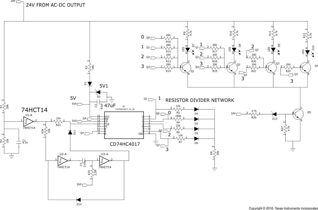
Figure 3 shows the working of an additional circuit. Whenever the AC is turned on, 24 V is formed at the output of the AC-DC section which is fed to the DRV10983 device. A 5-V supply is then formed to CD74HC4017 and 74HCT4017 using a Zener diode of 5V1. The 24 V is divided using a resistor divider and fed to the SN74HCT14 device to form 5 V at the input. If the AC is tuned off, 24 V goes to zero making the input of Inverter to zero and, because the 5-V supply is still present because of a high capacitor value, the output of inverter is high. And now, if the AC is turned on again, 24 V is formed at the AC-DC section and gives a high signal at the input of the inverter. The high signal at the input of the inverter provides a high-to-low signal at the output which is fed to the clock of the counter resulting in a change of the output state. Therefore, with each toggle of the AC mains Q0, Q1, Q2, and Q3 turn on consecutively. With each signal output, the resistor divider network forms different voltages between 0 and 3.3 V in four different levels that can be fed to the SPEED pin of the DRV10983 device for different speeds of the fan. Q4 is connected to the master reset (MR) to revert back to initial step. The number of steps of speed can be increased by increasing the use of the number of outputs and adjusting the resistor divider network accordingly.
 Figure 3. Proposed Solution to Control the Speed of the Fan by Toggling AC
 To achieve four different steps of speed, 0.8 V, 1.6 V, 2.4 V, and 3.3 V must be generated at the output of the network. If 20 kΩ is used at the output, the R4, R5, R6, and R7 resistors must be used at the outputs of the ring counter.
In the schematic, the closest available resistor values were used
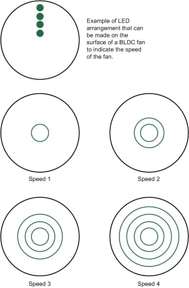
In addition, the output of Q0, Q1, Q2 and Q3 can be used to create an LED indication as shown in Figure 4. Whenever Q0 turns on, one LED turns on, and when Q1 turns on, two LEDs turn on, and so on. These LEDs can be kept on the surface of the ceiling fan which appears as a circle and variation of speed can be indicated with variation in size of circle accordingly.
 Figure 4. Probable LED Arrangement to Indicate the Speed of Fan