SLOA203 August 2016 DRV10983 , UCC28810
2.2 Additions to Input Filter for TRIAC Operation
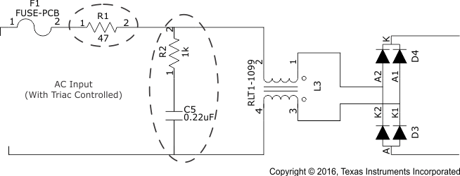
The resonance of the undamped EMI filter causes the input current, iin(t) to oscillate in response to the step change in the input voltage caused by the TRIAC firing action. Each time the input current falls below the holding current, ITH, the TRIAC commutates off. The internal RC timer initiates a new firing sequence leading to repeated firing and misfiring of the TRIAC. Therefore the transient response of the EMI filter must be controlled by incorporating suitable damping circuits. The standard method is to use RC snubber as shown in Figure 9.
A small value selected for R2 will cause the pole to move away from the zero while a large value for R2 will lead to insufficient damping of complex filter poles. As a result, a small optimal range of resistance between 100 Ω and 2 kΩ exists, which leads to a non-zero input current. This value can either be iteratively derived using simulation software or empirically estimated based on experimental data.
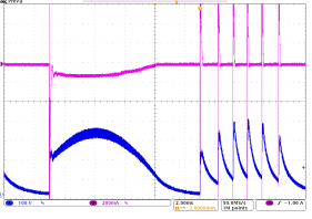
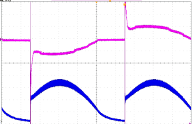
The TRIAC-chopped AC looks similar to the waveform shown in Figure 7. With addition of an R and C snubber, false triggering is eliminated and should result in the waveform shown in Figure 8.
 Figure 7. TRIAC Current and Input Rectified Voltage Without RC-Damped Circuit
 Figure 8. TRIAC Current and Input Rectified Voltage With RC-Damped Circuit
Rapid charging of the EMI filter capacitance during the firing sequence causes a large inrush current to flow through the TRIAC. A single series resistor, R1, shown in Figure 9, is required to limit the inrush current. The resistor also damps any high frequency oscillations caused by the internal TRIAC inductance or parasitic inductance and the EMI filter capacitance. The value of R1 is generally in the range of 10 Ω to 100 Ω and is limited by the acceptable power loss and efficiency. Improvement in efficiency is achieved by incorporating an active MOSFET-based bypass circuitry at the cost of additional components.
Figure 9 shows the addition of the Ri and RC snubber in the input filter section with the previously mentioned considerations.
 Figure 9. Input Resistor and RC-Damping Circuit Added to Input Filter