SLOA250C July 2017 – June 2022 TAS2505 , TAS2505-Q1
4.3 Diagnostic Circuit #2
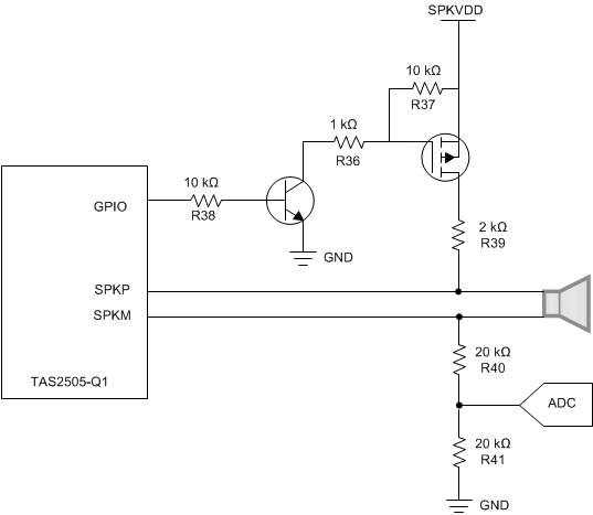
Figure 4-2 shows the second diagnostic circuit, which consists of only two transistors and six resistors. The first step is to mute the amplifier through software. The GPIO is set to an output, and pulling the GPIO high enables the circuit by biasing the BJT which turns on the p-channel MOSFET and allows current to flow from SPKVDD, across the speaker, and through the voltage divider created by R40 and R41. If the speaker is disconnected and there is an open circuit, then the voltage at the voltage divider is 0 V, but if there is a speaker connected and there is no fault, then the voltage divider is approximately 1.2 V. This voltage can be read from an external ADC, such as an analog input pin from a MCU to determine if there is an open circuit fault or not. The circuit should be disable by pulling the GPIO low before unmuting the amplifier and resuming normal operation.
 Figure 4-2 Diagnostic Circuit #2 Schematic