SLUA987C October 2019 – February 2023 UCC27531-Q1 , UCC28700-Q1 , UCC28730-Q1 , UCC28740-Q1 , UCC28C40-Q1 , UCC28C41-Q1 , UCC28C42-Q1 , UCC28C43-Q1 , UCC28C44-Q1 , UCC28C45-Q1
3 Start-Up Circuitry
Standby power is a critical requirement in battery-operated systems. Resistive start-up circuitry causes high quiescent losses at high input voltages. Therefore, an external, active start-up circuit, or a device with integrated HV start-up such as the UCC28730-Q1 or UCC28740-Q1, is recommended.
#T6011291-3 shows how an external, active start-up circuit can be implemented for a controller that utilizes resistive start-up, such as the UCC28C56H-Q1.
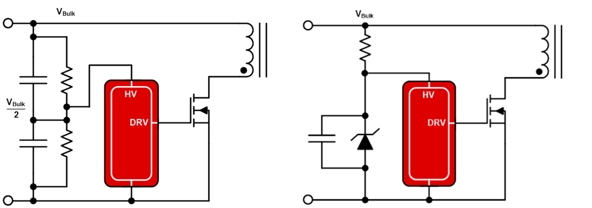
The UCC28730-Q1 and UCC28740-Q1 offer integrated 700-V start up, which enables operation directly off of a 400-V battery, but not an 800-V battery. As shown in #T6011291-1, powering the start-up circuit from the center point of a stacked capacitor bank, or using a clamp circuit to clamp the voltage, enables operation directly off of an 800-V battery.
 Figure 3-2 Implementation to Support > 700 V Inputs
The UCC28700-Q1, and UCC28730-Q1 and UCC28740-Q1 variable frequency, peak current-mode flyback controllers and the UCC28C56H-Q1 fixed-frequency, peak current-mode PWM controller offer a wide UVLO hysteresis that allows for more headroom on the VDD voltage before triggering UVLO, which provides long soft-start times and requires less capacitance on the VDD pin.