SLVA488B January 2014 – January 2021 DRV8434 , DRV8811 , DRV8818 , DRV8821 , DRV8824 , DRV8825
3 I2C Protocol and Communications Engine
In order to program the device parameters and the stepper motion engine profiles, an I2C protocol was chosen. The way it was designed, up to four controllers can be cascaded with only two communication lines and two address selector lines.
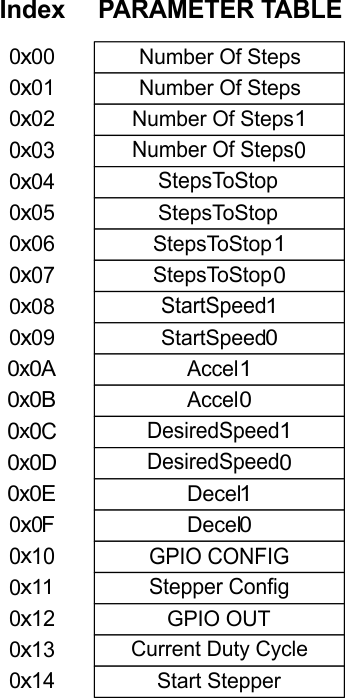
The I2C protocol is the typical three byte packet where the first byte is the target address, the second byte is the register address and the third byte is the data. There are 21 possible address register which can be accessed.
 Figure 3-1 Parameters Table
The variables residing on addresses 0x00 to 0x0F have been discussed on previous sections. The other addresses are a combination of parameters as well as actions.