SLVAE30E February   2021  – March 2021 TPS1H000-Q1 , TPS1H100-Q1 , TPS1H200A-Q1 , TPS1HA08-Q1 , TPS25200-Q1 , TPS27S100 , TPS2H000-Q1 , TPS2H160-Q1 , TPS2HB16-Q1 , TPS2HB35-Q1 , TPS2HB50-Q1 , TPS4H000-Q1 , TPS4H160-Q1


  1.   Trademarks
  2. 1Introduction
  3. 2Driving Resistive Loads
    1. 2.1 Background
    2. 2.2 Application Example
    3. 2.3 Why Use a Smart High Side Switch?
      1. 2.3.1 Accurate Current Sensing
      2. 2.3.2 Adjustable Current Limiting
    4. 2.4 Selecting the Right Smart High Side Switch
      1. 2.4.1 Power Dissipation Calculation
      2. 2.4.2 PWM and Switching Loss
  4. 3Driving Capacitive Loads
    1. 3.1 Background
    2. 3.2 Application Examples
    3. 3.3 Why Use a Smart High Side Switch?
      1. 3.3.1 Capacitive Load Charging
      2. 3.3.2 Inrush Current Mitigation
        1. 3.3.2.1 Capacitor Charging Time
      3. 3.3.3 Thermal Dissipation
      4. 3.3.4 Junction Temperature During Capacitive Inrush
      5. 3.3.5 Over Temperature Shutdown
      6. 3.3.6 Selecting the Correct Smart High Side Switch
  5. 4Driving Inductive Loads
    1. 4.1 Background
    2. 4.2 Application Examples
    3. 4.3 Why Use a Smart High Side Switch?
    4. 4.4 Turn-On Phase
    5. 4.5 Turn-Off Phase
      1. 4.5.1 Demagnetization Time
      2. 4.5.2 Instantaneous Power Losses During Demagnetization
      3. 4.5.3 Total Energy Dissipated During Demagnetization
      4. 4.5.4 Measurement Accuracy
      5. 4.5.5 Application Example
      6. 4.5.6 Calculations
      7. 4.5.7 Measurements
    6. 4.6 Selecting the Correct Smart High Side Switch
  6. 5Driving LED Loads
    1. 5.1 Background
    2. 5.2 Application Examples
    3. 5.3 LED Direct Drive
    4. 5.4 LED Modules
    5. 5.5 Why Use a Smart High Side Switch?
    6. 5.6 Open Load Detection
    7. 5.7 Load Current Sensing
    8. 5.8 Constant Current Source
      1. 5.8.1 Selecting the Correct Smart High Side Switch
  7. 6Appendix
    1. 6.1 Transient Thermal Impedance Data
    2. 6.2 Demagnitization Energy Capability Data
  8. 7References
  9. 8Revision History

Turn-On Phase

GUID-701398A0-75C3-406D-9C6E-CF3FBB48A9C4-low.gif Figure 4-2 Inductive Load Turn-On Phase

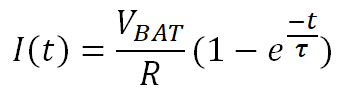
The turn-on phase as shown in Figure 4-2 begins when the supply voltage VBAT is initially applied to an uncharged inductive load. This causes the load current to ramp up exponentially from zero. When a step voltage VBAT is applied across an uncharged inductor, the current can be calculated with Equation 29.

Equation 29. GUID-20200811-CA0I-CFVC-L17C-RDWPH9PTBN6K-low.png
Equation 30. GUID-20200811-CA0I-LMFL-PXJT-DNRLRLTDXFFJ-low.png

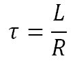
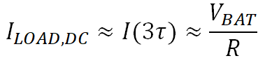
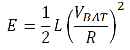
The time constant τ determines the slew rate of the current and is a function of the load resistance and inductance. The load profile also determines the steady state current ILOAD,DC through Equation 31, which is approximately reached at time t = 3τ and the stored magnetic energy E through Equation 32.

Equation 31. GUID-20200811-CA0I-0QSL-DZBK-0FG784WFV8TD-low.png
Equation 32. GUID-20200811-CA0I-VTN7-XW11-PXBKZZ6GCC3L-low.png

When using a Smart High Side Switch that includes open load detection, make sure that the switch waits long enough for the current to ramp before declaring an open load. Also ensure that the Smart High Side Switch can handle the DC current flow. If the current is above the data sheet specification of the device it can cause high power dissipation inside the switch and cause a thermal shutdown.