SLVAE59A February 2019 – April 2022 DRV8242-Q1 , DRV8243-Q1 , DRV8244-Q1 , DRV8245-Q1 , DRV8343-Q1 , DRV8702-Q1 , DRV8702D-Q1 , DRV8703-Q1 , DRV8703D-Q1 , DRV8803 , DRV8804 , DRV8805 , DRV8806 , DRV8860 , DRV8873 , DRV8873-Q1 , DRV8874 , DRV8874-Q1 , DRV8876 , DRV8876-Q1 , DRV8935 , DRV8955
3.1 Current Control
Driving solenoids with current control requires two things: current sense and current regulation. The advantages of current control are improved efficiency and reliability across temperature. As the solenoid or relay coil heats up from I2R losses or is warmed by its environment, the coil resistance increases. With the current-sense feedback, the current can be monitored and adjusted to produce a constant force even with the changes in resistance.
The second advantage is that it can provide some measure of protection from higher than rated supply voltage. Solenoids have voltage ratings because they can be destroyed by too much current going through the coil, which happens when driving at higher voltages. This problem can be managed with current-sense feedback, and by controlling the current going through the solenoid regardless of the supply voltage. This allows a single solenoid driver design to be reused on multiple products.
There are two methods for providing load current feedback from motor driver IC to a microcontroller. One method is from a current shunt amplifier using an external sense resistor that is connected either in line with the load, or on the high- or low-side. The other is from a current mirror, which provides a proportional current to load current to pin output, removing the need for an external sense resistor. This proportional current output method is available for motor driver ICs with integrated MOSFETs. One limitation here is that generally, both high- and low-side sense output may not always be available for a given integrated motor driver IC.
To regulate current and energize and de-energize most solenoids, peak-and-hold drive is desired. Figure 3-1 below shows an example of this expected peak-and-hold current.
The charging current is drawn or driven into the solenoid, called the peak current. The current in the solenoid will ramp to its peak, at which point the magnetic field will depress the plunger into the spring. To maintain the solenoid in this position, current must still be drawn or driven into the solenoid. This is referred to as hold current. However, this current is far lower than the peak current. To further minimize power dissipation through the solenoid during hold phase, the hold current can be regulated.
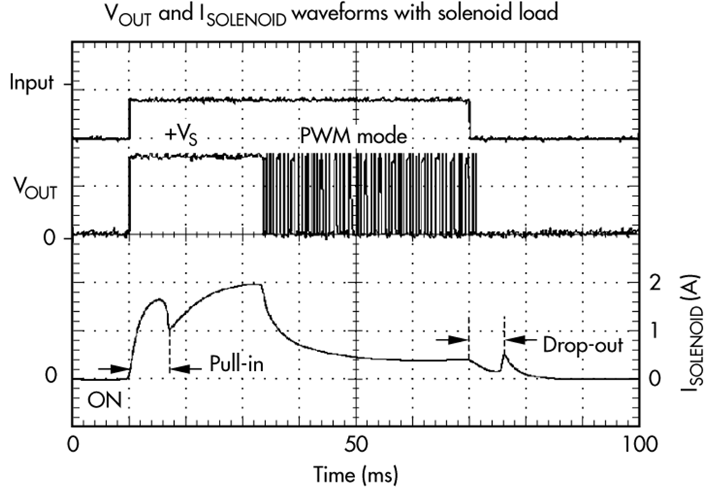
Just as pulse width modulation (PWM) is used to drive other types of motors, it also can be used to drive solenoids. PWM can be used to regulate the current of a solenoid to different levels at different times by varying the duty cycle. This allows the user drive a longer or maximum duty cycle to pull in the solenoid, and then a shorter duty cycle to hold it in place, optimizing the power consumption. Figure 3-2 shows the current and voltage driving outputs for the PWM implementation.
 Figure 3-2 Solenoid Voltage and Current
Outputs Using PWM
Figure 3-2 Solenoid Voltage and Current
Outputs Using PWMThis reduces power consumption of the solenoid solution, due to the lower current in the coil. If the drive current is not reduced, power dissipation will heat up the solenoid further. With the increase in temperature the solenoid initial resistance will also increase, all of which can lead to unintentional de-actuation or failing to actuate the solenoid. Note in the above screenshot that the drop-out or de-actuation time is roughly 10 ms.