SLVAER8A April 2020 – October 2020 TPS63900 , TPS63901
1 Introduction
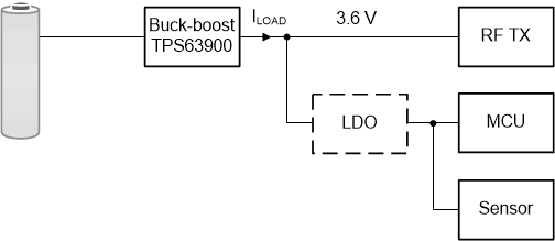
In many applications, it is necessary to continuously power a system, or at least some parts within a system. An example is a wireless sensor that needs to take continuous measurements, and periodically transmit them. A power tree of one such system is shown in Figure 1-1. Often in such applications the battery current is very low for most of the time, in orders of μA. Periodically, the system wakes up and the current consumption rises up to hundreds of mA during data transmission.
To accommodate the wide range of battery operating voltage, a switching converter typically provides stabilized voltage for the system. If all the parts share the same voltage rail, the voltage is determined by the part that requires the highest minimum voltage to operate properly or with the required performance. In the example from Figure 1-1, it is the wireless transmitter that requires 3.6 V to achieve the required range for data transmission. The other parts can be powered from the same rail, or via a secondary smaller linear regulator if their operating voltage is lower.
 Figure 1-1 Power Tree of a Wireless Sensor
Often, the transmission takes place sporadically and most of the time the system is in low-power mode with the converter operating with very light load. Figure 1-2 shows an example of such a load profile with very low duty cycle D.
 Figure 1-2 Typical Current Consumption in Wireless Sensors
To maximize the battery life, it is important that the converter has high efficiency so that the amount of power lost during conversion is as small as possible. Moreover, the efficiency has to be high at both high and low load currents, which are often two contradicting requirements when designing a converter. However, if the duty cycle D is sufficiently low, the efficiency at light loads becomes more important. For more details, see Selecting a DC/DC Converter for Maximum Battery Life in Pulsed-Load Applications.
When assessing the converter performance at very light loads, an often used parameter is the quiescent current, or IQ. IQ is defined as the current drawn by the device in a no-load and non-switching but enabled condition. In general, smaller quiescent current means that the converter is more efficient at very light loads. For a detailed explanation of the quiescent current and how it relates to the efficiency, see the IQ: What It Is, What It Isn’t, and How to Use It Technical Brief.
Designers are putting tremendous efforts to decrease IQ and improve the converter efficiency at light loads. At μA load current levels, often an LDO has an advantage over a switching converter, unless the voltage needs to be boosted. Not having a sufficiently low IQ sometimes requires combining a switching converter with an LDO as shown in the Adding an LDO for Increased Standby Mode Efficiency Reference Design, or using a switching converter with an integrated LDO. This approach comes with the price of increased solution size and cost.
Now looking at the required external components, there is often a resistive feedback divider used to set the output voltage. When the load is in the range of a few μA, the current consumption of this feedback divider alone can take a significant portion of the total current consumption. To overcome this, some devices, such as the TPS63900, use set resistors to set the output voltage during start-up. This together with other design improvements leads to the extremely small IQ of only 75 nA. Therefore, this switching converter can compete against linear regulators even in the μA current range.
As the next step in increasing the system efficiency, the supply voltage can be dynamically scaled to accommodate different power needs. Looking back at Figure 1-1, the voltage rail is set to 3.6 V due to the transmitter power requirements for achieving a reliable data transmission. The same voltage is kept during standby, even though the rest of the system can operate at lower voltages. This is an unnecessary waste of power. Instead, the voltage rail can be lowered to a level that is just enough for the sensor and the microcontroller to operate. The TPS63900 has an additional feature that the output voltage can be dynamically switched between two user-configurable levels. This can lead to significant improvements in the system efficiency, as will be shown in the following case study.