SLVAFO8A April 2024 – May 2024 DRV8214 , DRV8234
- 1
- Abstract
- Trademarks
- 1Introduction: Need for Sensorless Designs
- 2Ripple Counting − Concept
- 3Case Study: Robotic Wheel Drive
- 4Challenges and Workarounds
- 5Summary
- 6References
- 7Revision History
3.3.1.1 Motor Speed Calculation
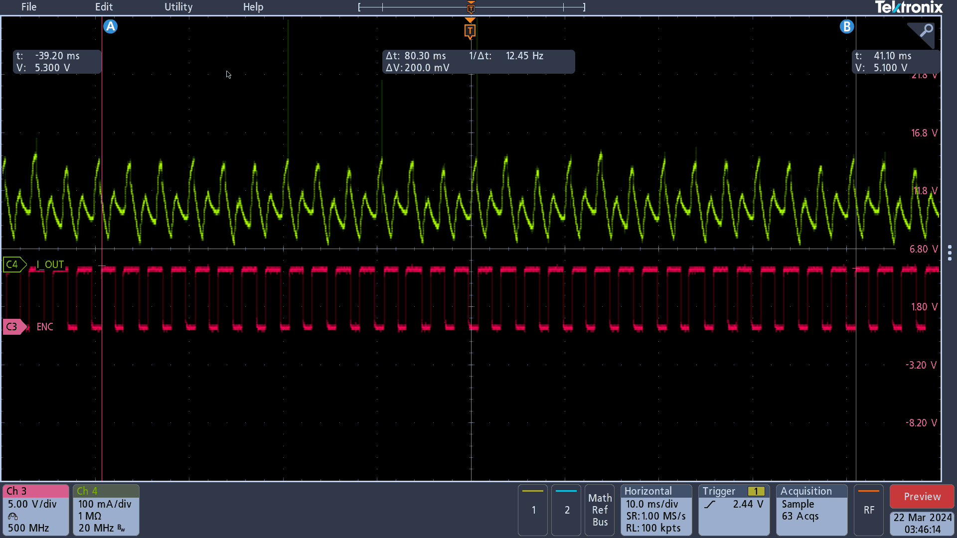
To calculate motor speed and verify that ripple counting gives out accurate motor speed, we need to know the actual motor speed first. This is done with the help of the encoder. From Figure 3-5, the encoder gives out 32 pulses in 80.3ms. Since the encoder also gives out 4 pulses per motor rotation, the actual motor speed, is given by:
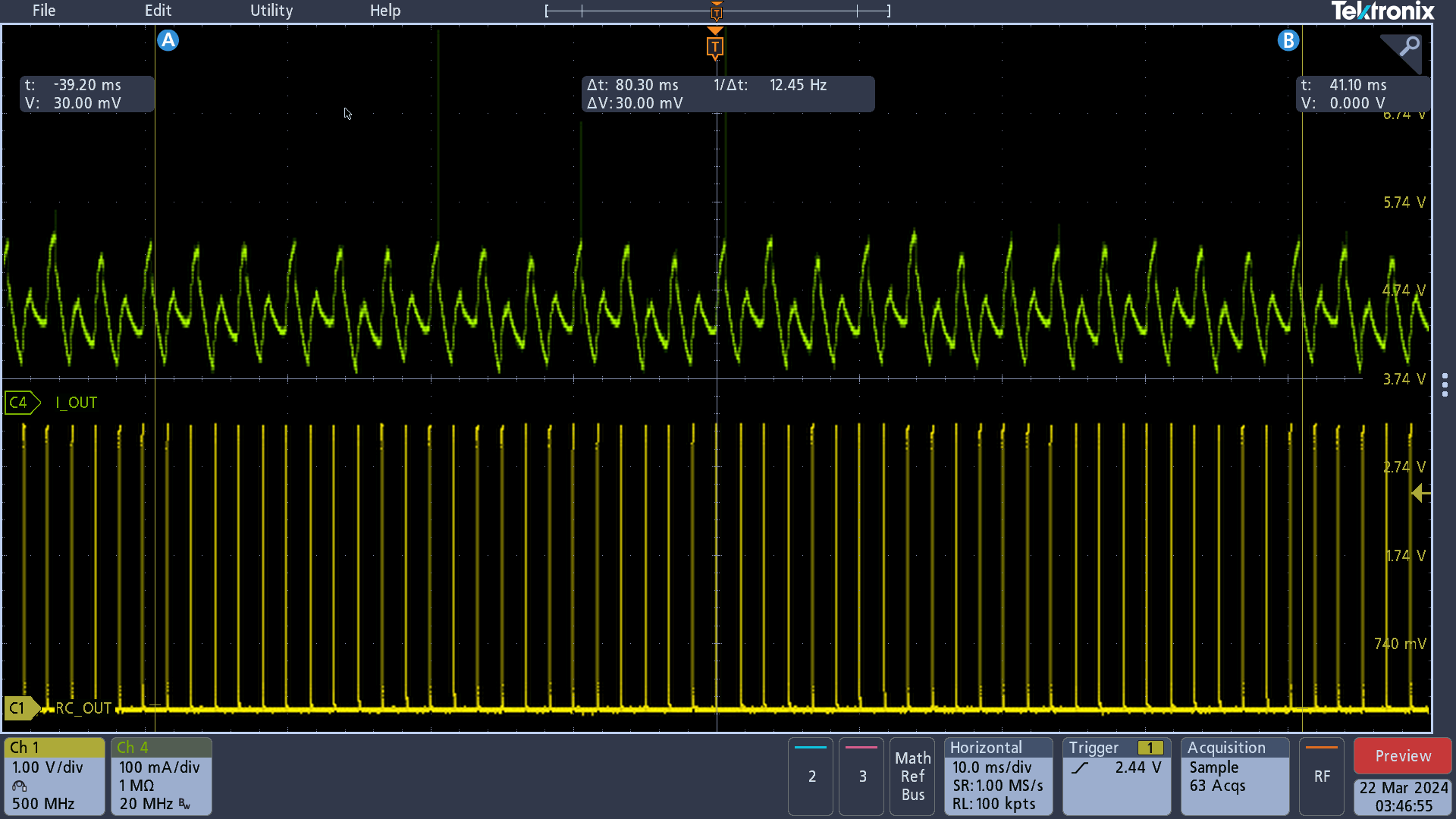
From Figure 3-6, the RC_OUT pin gives out 48 pulses in 80.3ms. Since RC_OUT gives out 6 pulses per motor rotation, the calculated motor speed using RC_OUT is given by:
Thus, ripple counting output matches encoder output during steady state conditions.
 Figure 3-5 Actual Motor Speed Using
Encoder
 Figure 3-6 Motor Speed Calculated Using
RC_OUT