SLVUBE9A March   2018  – June 2021 TPS62148


  1.   Trademarks
  2. 1Introduction
    1. 1.1 Performance Specification
    2. 1.2 Modifications
      1. 1.2.1 Input and Output Capacitors
      2. 1.2.2 Soft-Start Time
      3. 1.2.3 Configurable Tracking Voltage
      4. 1.2.4 Configurable Enable Threshold Voltage
      5. 1.2.5 Loop Response Measurement
  3. 2Setup
    1. 2.1 Connector Descriptions
    2. 2.2 Hardware Setup
  4. 3TPS62148EVM-034 Test Results
  5. 4Board Layout
  6. 5Schematic and Bill of Materials
    1. 5.1 Schematic
    2. 5.2 Bill of Materials
  7. 6Revision History

Board Layout

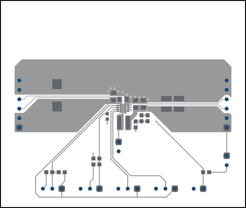
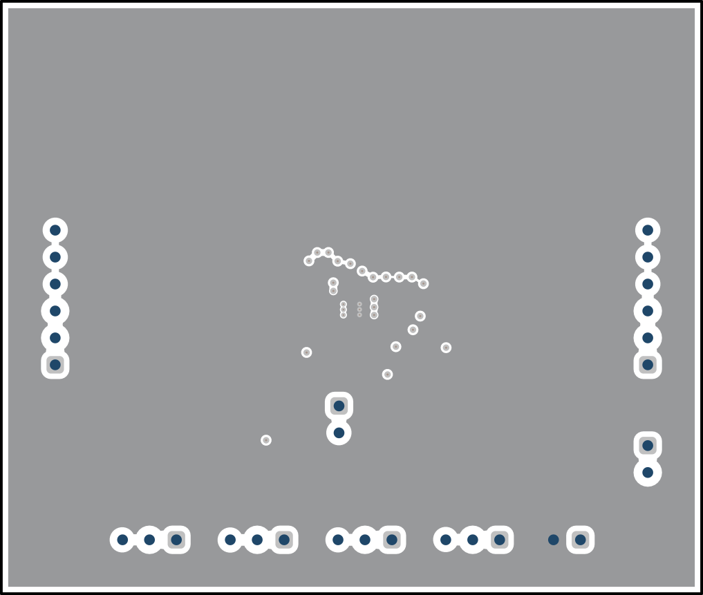
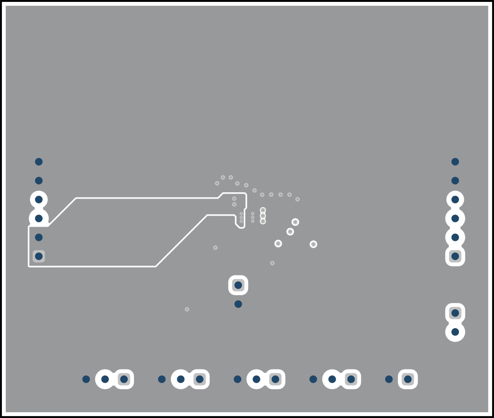
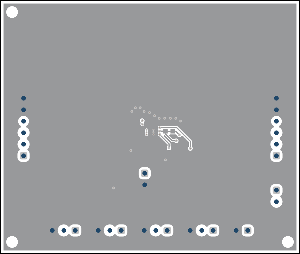
This section provides the TPS62148EVM-034 board layout and illustrations. The Gerbers are available on the EVM product page: TPS62148EVM-034.
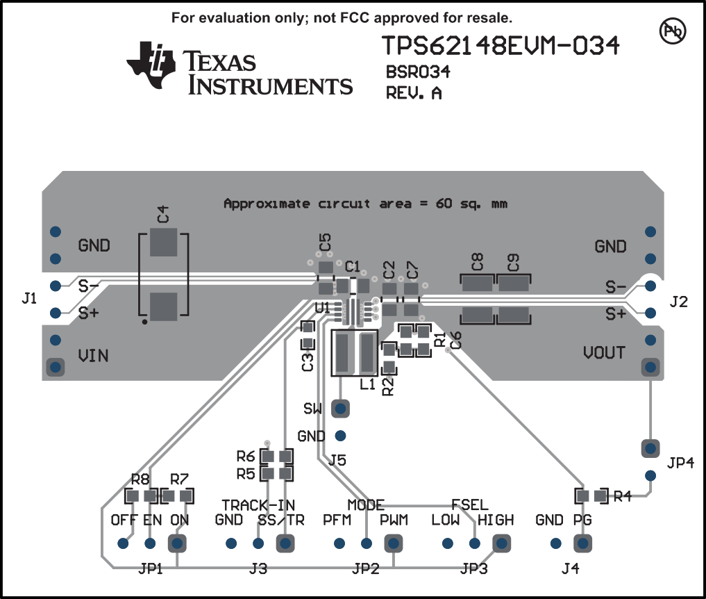
GUID-41E08440-A0EC-4E49-9EB3-2451964ACB08-low.gifFigure 4-1 Assembly Layer
GUID-7AA80E16-5A37-4459-AA66-76B10DEEF2F8-low.gifFigure 4-2 Top Layer
GUID-39A50FD6-D18D-4E81-89DF-98A44E7D10FD-low.gifFigure 4-3 Internal Layer 1
GUID-59B02A0C-1FE7-4FED-8BD9-5588DA2EEAA1-low.gifFigure 4-4 Internal Layer 2
GUID-A65A0B99-A720-46F9-ABCF-A466E0EEF1F0-low.gifFigure 4-5 Bottom Layer