SLVUBZ4 February 2021 TPS25750
3 Example Configuration
This section will walk through setting up a new configuration, filling out the form, and flashing to the device. A TPS25750EVM is needed to execute the final step. If one is not available, the remainder of the example can still be followed.
- Select the New Configuration button on the right side panel. See Figure 3-1.
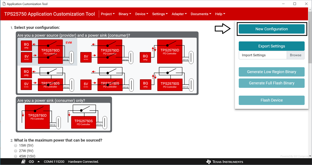 Figure 3-1 Button to generate a new
configuration is pointed to by the arrow
Figure 3-1 Button to generate a new
configuration is pointed to by the arrow- When the modal appears, click the red New configuration button, as shown in Figure 3-2. This will reset any existing configuration on the form.
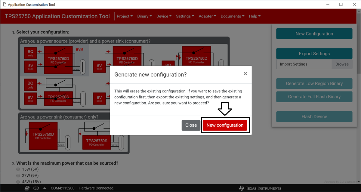 Figure 3-2 New configuration can be generated
by clicking the button pointed to by the arrow
Figure 3-2 New configuration can be generated
by clicking the button pointed to by the arrow- Question one should already be filled out. Ensure that the top-left option is selected.
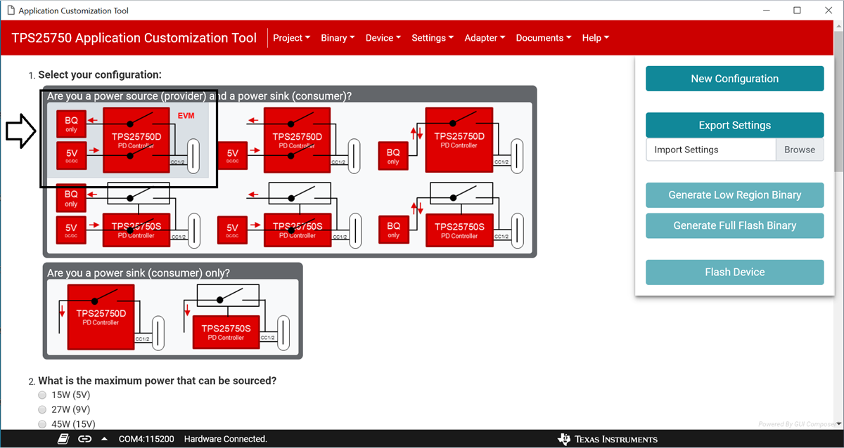 Figure 3-3 Ensure that the option outlined in
black is selected
Figure 3-3 Ensure that the option outlined in
black is selected- Question two should also be answered already. Ensure that 100W (20V) is selected. See Figure 3-3.
- Question three should already be filled out as well. Ensure that 100W (20V) is selected. See Figure 3-3.
- Question four should also be filled out. Ensure that Host & Device - Dual Role Port (DRP) is selected. See Figure 3-3.
- Select Power source (provider) as the answer to question five. See Figure 3-3.
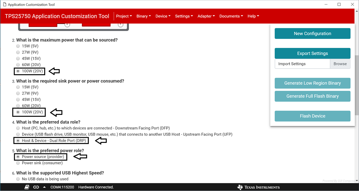 Figure 3-4 Ensure that the options pointed to
by the arrows are selected
Figure 3-4 Ensure that the options pointed to
by the arrows are selected- Select the USB 3.2 Gen 2 option for question six.
- For question seven, select No, use the TI Vendor ID in the Vendor Information File (VIF).
- For question eight, select No, use '0x0000' as the Product ID.
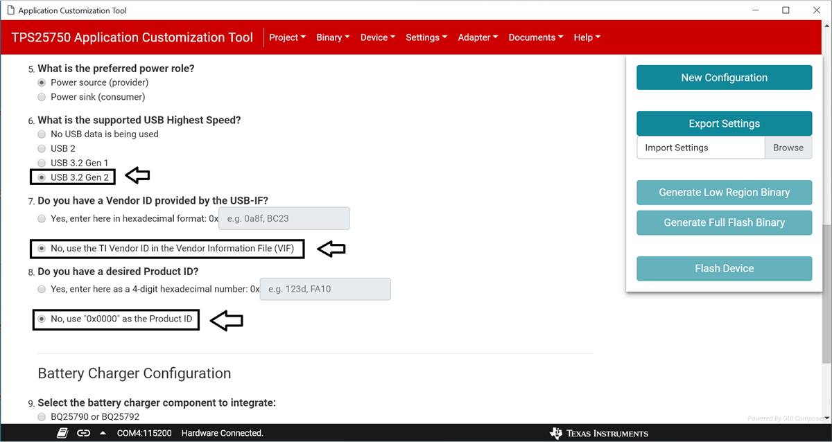 Figure 3-5 Ensure that the options pointed to
by the arrows are selected
Figure 3-5 Ensure that the options pointed to
by the arrows are selected- Select BQ25790 or BQ25792 as the battery charger to integrate for question nine.
- Enter 3.7V as the battery charging voltage for the question ten.
- Enter 1A as the battery charging current for the question eleven.
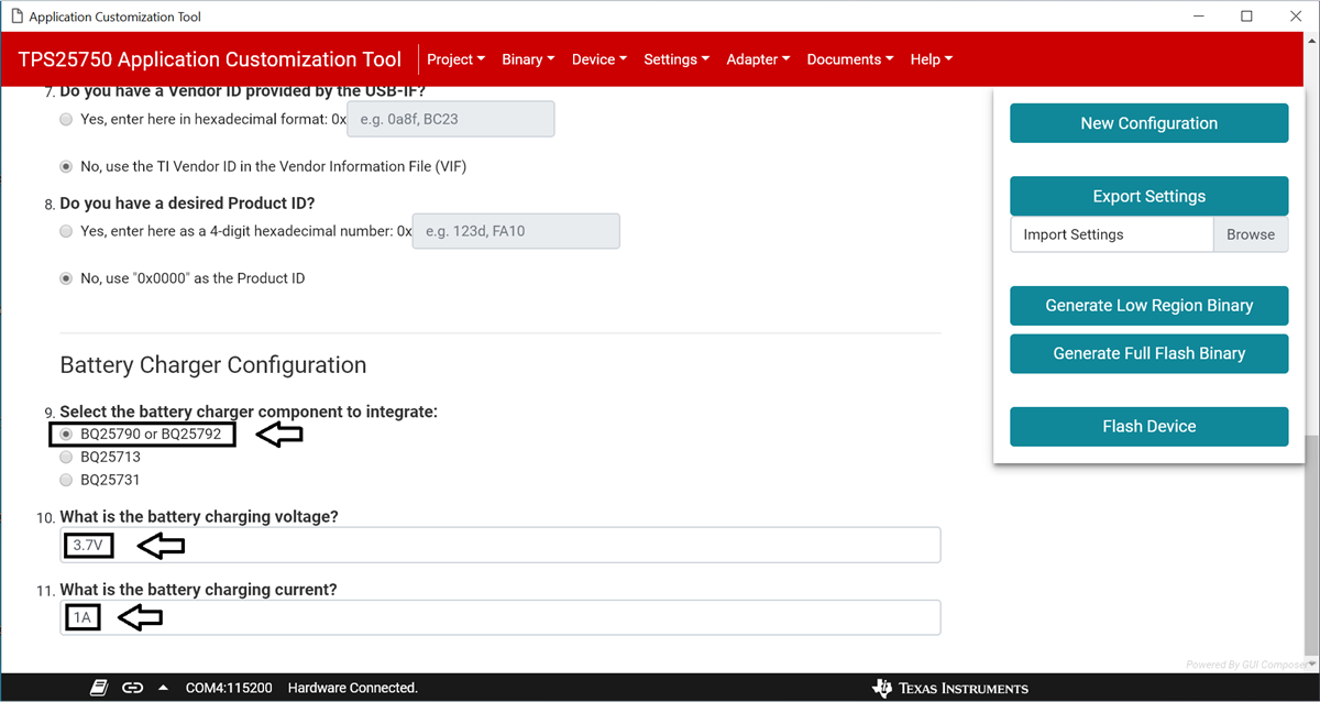 Figure 3-6 Ensure that the answers to the
battery charger questions match those shown by the arrows
Figure 3-6 Ensure that the answers to the
battery charger questions match those shown by the arrows- The Flash Device button on the right side panel should now be enabled. Ensure that the TPS25750EVM is physically connected to the computer through USB, and click the Flash Device button to upload the new settings onto the device.
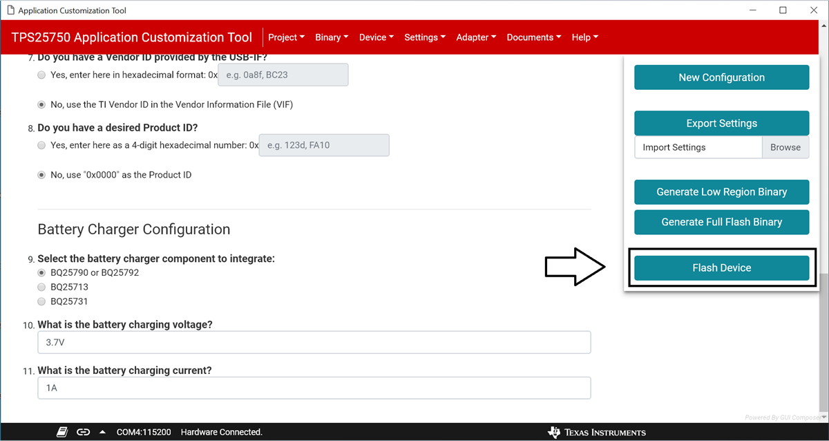 Figure 3-7 After filling out the form, click the button
to flash to the device, pointed to by the arrow