SLYT820 February 2022 AMC22C11 , AMC22C12 , AMC23C10 , AMC23C11 , AMC23C12 , AMC23C12-Q1 , AMC23C14
- 1Introduction
- 2Introduction to electric motor drives
- 3Understanding fault events in electric motor drives
- 4Achieving reliable detection and protection in electric motor drives
- 5Use case No. 1: Bidirectional in-phase overcurrent detection
- 6Use case No. 2: DC+ overcurrent detection
- 7Use case No. 3: DC– overcurrent or short-circuit detection
- 8Use case No. 4: DC-link (DC+ to DC–) overvoltage and undervoltage detection
- 9Use case No. 5: IGBT module overtemperature detection
8 Use case No. 4: DC-link (DC+ to DC–) overvoltage and undervoltage detection
The DC-link voltage should be within the specified range for proper operation of the motor drive. The AMC23C14 can be a good choice for detecting overvoltage and undervoltage conditions.
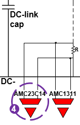
As shown in location 4 of Figure 8-1, the bottom resistor of a resistor-divider network produces a voltage drop that is sensed by the AMC23C14 dual reinforced window comparator.
 Figure 8-1 DC-link overvoltage and
undervoltage detection.
Figure 8-1 DC-link overvoltage and
undervoltage detection.The AMC23C14 has two open-drain outputs, OUT1 and OUT2, one for each window comparator. OUT1 actively pulls low when the input voltage exceeds the pre-defined threshold valuesof the voltage on the reference pin for the purposes of undervoltage detection. OUT2 actively pulls low when the input voltage exceeds the threshold values defined by the internal 300-mV reference for the purposes of overvoltage detection. Figure 8-2 shows the OUT1 and OUT2 outputs for overvoltage and undervoltage events. If you only require overvoltage detection, you can use the AMC23C11.