SLYT826 April 2022 DRV5055 , DRV5056 , TMAG5170 , TMAG5273
2 Magnet-to-sensor orientations
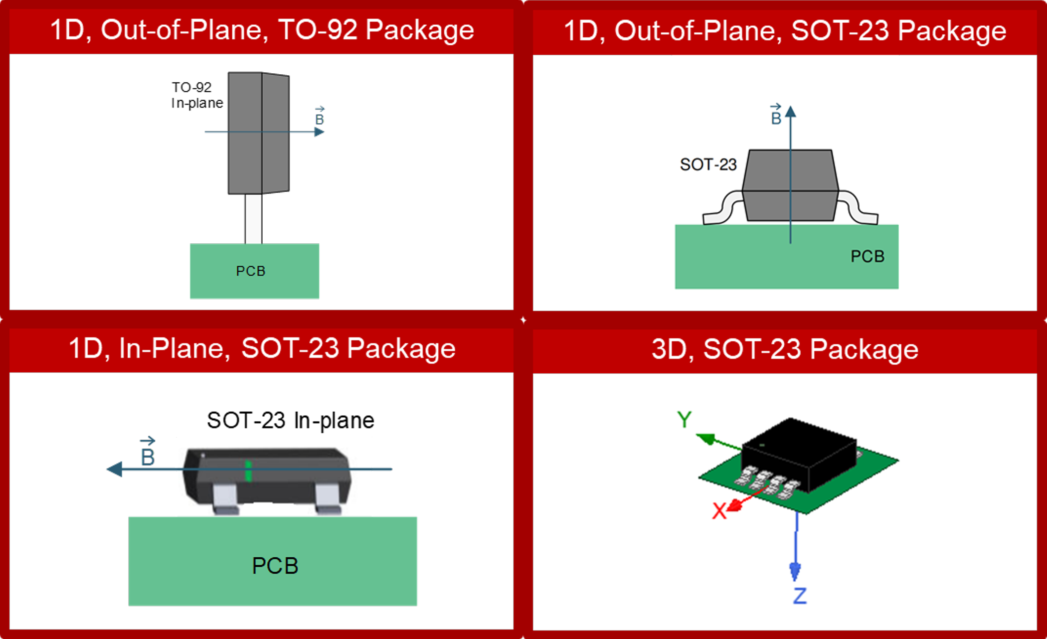
When using one-dimensional (1D) Hall-effect sensors, the direction of sensor sensitivity partially determines where you can place the magnet with respect to the sensor. If a sensor is an out-of-plane sensor, which is the most common case with Hall-effect sensors, the out-of-plane sensor is sensitive to the magnetic field component that is perpendicular to the die inside the package.
For surface-mount out-of-plane 1D sensors such as the small outline transistor (SOT)-23 package shown at the top right in Figure 2-1, the Hall-effect sensor senses the magnetic field component that is perpendicular to the printed circuit board (PCB) surface.
 Figure 2-1 Clockwise from bottom left:
direction of sensitivity for 1D in-plane, 1D out-of-plane, 1D out-of-plane and
3D sensors.
Figure 2-1 Clockwise from bottom left:
direction of sensitivity for 1D in-plane, 1D out-of-plane, 1D out-of-plane and
3D sensors.For through-hole sensors such as the transistor outline (TO)-92 package at the top left in Figure 2-1, the Hall-effect sensor senses the magnetic field component that is perpendicular to the marked side of the package. If the through-hole sensor is positioned to be perfectly vertical, the Hall-effect sensor will be sensitive to the magnetic field component that is parallel to the PCB.
In contrast, if the sensor is an in-plane sensor, it is sensitive to a magnetic field component that is coplanar to the device’s die. The bottom-left illustration in Figure 2-1 shows an in-plane sensor. Since the direction of sensitivity of this in-plane SOT-23 device is the same as the out-of-plane TO-92 device in Figure 2-1, the surface mount in-plane SOT-23 device can replace the through-hole out-of-plane TO-92 device and maintain the same direction of sensor sensitivity.
For increased magnet placement flexibility, you could also use a linear 3D Hall-effect sensor such as the TMAG5170 or TMAG5273, as shown at the bottom right in Figure 2-1. Implementations of these devices often entail using two in-plane sensors and one out-of-plane sensor for implementing 3D sensing. Since they are not restricted to sensing in only one direction, 3D sensors are the best option for sensing complex magnetic fields from magnets.
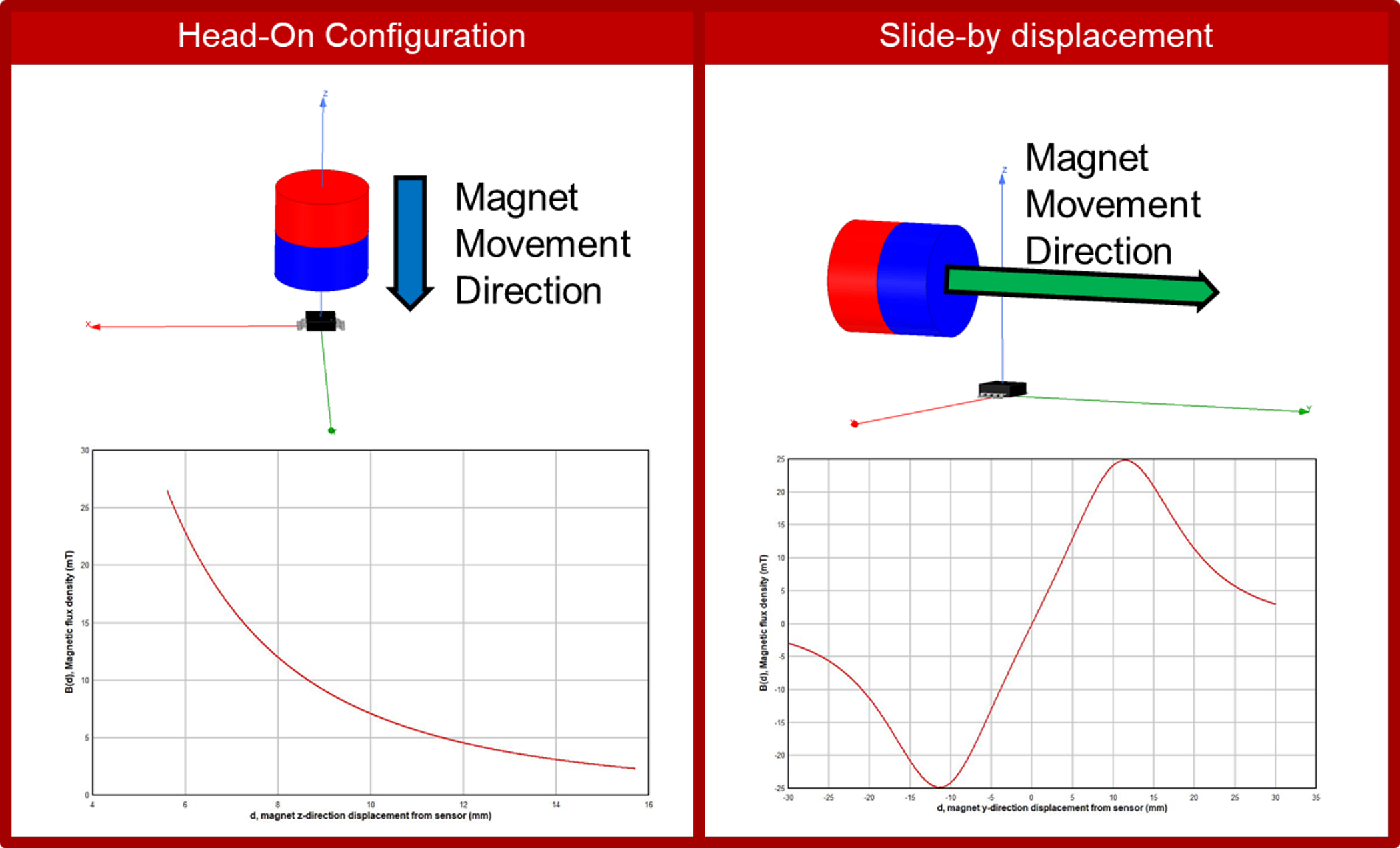
One common magnet-to-sensor configuration is the head-on configuration shown in Figure 2-2(a), where the path of travel is along the direction of sensitivity. This particular out-of-plane SOT-23 package has a direction of sensitivity in the z axis. The magnet in this configuration also moves along the z axis and has a polarization in the z direction as well, which results in the sensor seeing only a positive or negative field, also shown in Figure 2-2(a).
Figure 2-2(b) shows a slide-by-displacement configuration in which the Hall-effect sensor senses the magnetic field component in the z direction, but the magnet moves in the y direction. The sensor is offset, but not in the traveling path. For this configuration, the sensor sees positive and negative fields if both the south and north poles of the magnet go past the sensor, as shown in the magnetic flux density graph in Figure 2-2(b).
 Figure 2-2 Magnet-to-sensor
configurations: head-on (a); slide-by-displacement (b).
Figure 2-2 Magnet-to-sensor
configurations: head-on (a); slide-by-displacement (b).When selecting the output of a Hall-effect sensor, you may also need to consider the sign of the applied magnetic field. Different devices have different ways of defining a positive or negative field.
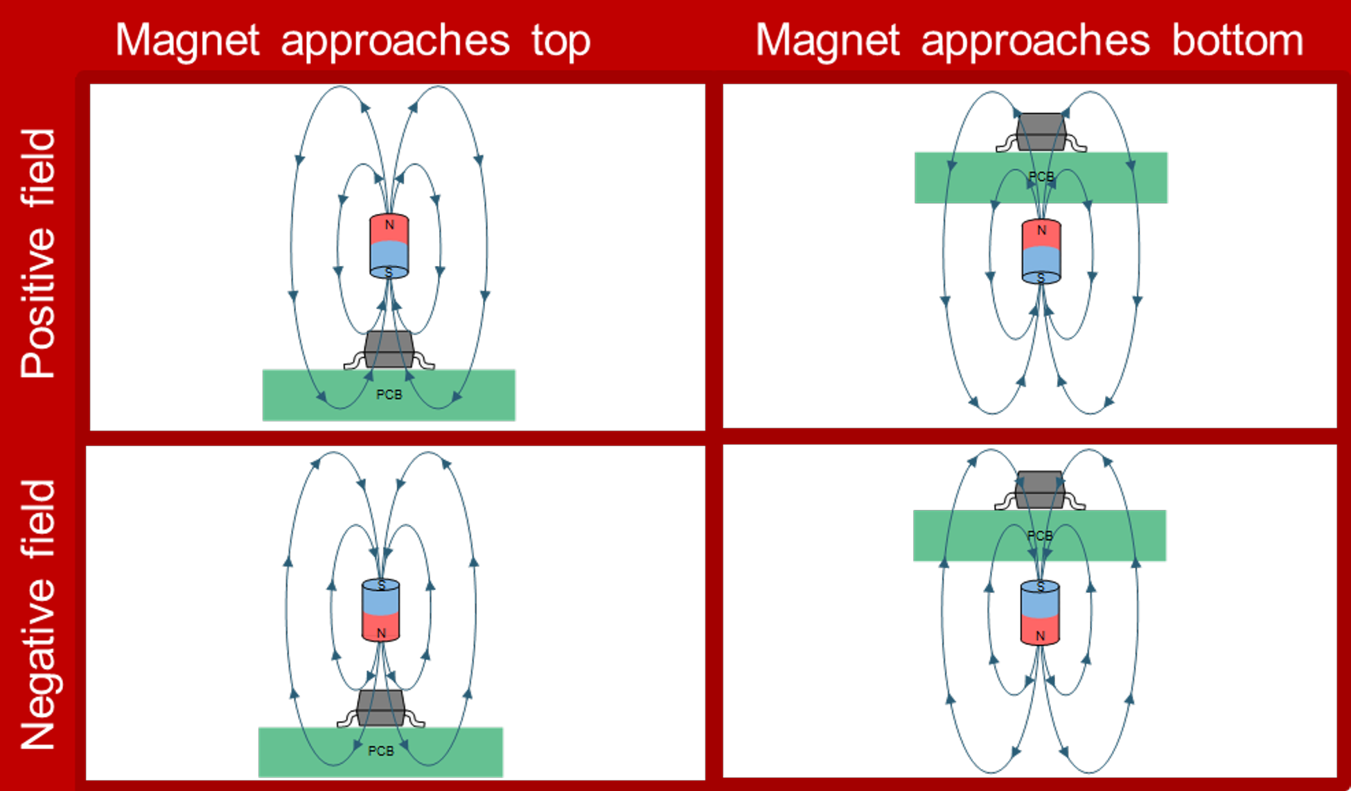
For example, assume that the surface mount out-of-plane device in Figure 2-3 defines a positive field as having magnetic flux traveling from the bottom to the top of the package, and a negative field as having magnetic flux traveling from the top to the bottom of the package. You will see a positive field when applying the south pole of a magnet directly above the sensor, or when applying the north pole of a magnet directly beneath the sensor. You must select the appropriate output polarity to properly sense the magnetic field generated by the magnet.
Bipolar linear Hall-effect sensors such as the DRV5055 detect both positive and negative fields, while unipolar sensors such as the DRV5056 detect either positive or negative fields. Since unipolar sensors only sense one polarity, they may have more sensing resolution compared to the corresponding bipolar device; however, since bipolar devices work with both poles of a magnet, it allows the magnet to be placed without determining whether a pole of the magnet is the south or north pole.
 Figure 2-3 Example polarity of an SOT-23
out-of-plane sensor.
Figure 2-3 Example polarity of an SOT-23
out-of-plane sensor.For more information on the head-on and slide-by configurations or different Hall-effect sensor outputs, see the TI training video, Introduction to Head-On Applications