SNIU049 May 2021 TMP126 , TMP126-Q1 , TMP127-Q1
5.3 Settings Tab
The Settings tab provides the hardware configuration for the USB to I2C bridge and device features for the TMP126 device.
Selecting the wrong Device I2C Address will cause the GUI to disconnect from the USB device. To use the EVM with a different address, a swap out of the TMP126 device would be required. The link icon in the bottom left corner indicates the current connection status, and the user can click on the area to change the connection status.
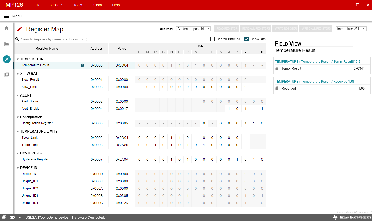
The other widgets within the settings tab may be used to easily configure the settings of the TMP126. How these changes are written on the I2C bus will depend on the settings in the registers tab. For example, if the user makes changes to the High and Low Limit sliders, this will trigger an immediate write to the TMP126's limit registers only if Immediate mode is enabled on the Registers tab.
 Figure 5-3 Settings