SNOA930C March 2015 – May 2021 LDC0851 , LDC1001 , LDC1001-Q1 , LDC1041 , LDC1051 , LDC1101 , LDC1312 , LDC1312-Q1 , LDC1314 , LDC1314-Q1 , LDC1612 , LDC1612-Q1 , LDC1614 , LDC1614-Q1 , LDC2112 , LDC2114 , LDC3114 , LDC3114-Q1
2.5.1 Measurement of SRF
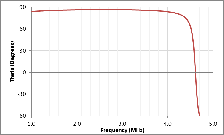
The SRF of an inductor can be easily measured with an impedance analyzer. With an impedance analyzer, the SRF is measured by simply connecting the inductor and plotting the magnitude of the impedance and phase versus frequency. The frequency at which θ=0° corresponds to the SRF. In the example shown in Figure 2-15, the SRF occurs at 4.6 MHz. Note that the SRF is a function of the target interaction — when the target is interaction is stronger, the SRF almost always increases.
 Figure 2-15 Inductance T Versus Frequency
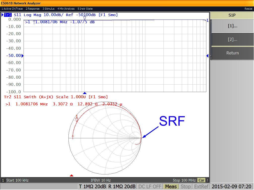
A Vector Network Analyzer (VNA) is also able to perform this measurement. As always with VNAs, it is important to properly calibrate the VNA. The calibration plane must be at the connections to the inductor, otherwise the offset introduces a transmission line into the measurement that results in a measurement error. Once calibrated, simply measure S11 over an appropriate frequency span. The SRF is the frequency where the S11 graph crosses the real axis close to the open, as indicated in Figure 2-16.
 Figure 2-16 Measurement of SRF with a VNA