SNOA954D November   2019  – June 2021 LDC0851 , LDC1001 , LDC1001-Q1 , LDC1041 , LDC1051 , LDC1101 , LDC1312 , LDC1312-Q1 , LDC1314 , LDC1314-Q1 , LDC1612 , LDC1612-Q1 , LDC1614 , LDC1614-Q1 , LDC2112 , LDC2114 , LDC3114 , LDC3114-Q1


  1.   Trademarks
  2. 1LDC Applications
    1. 1.1 Axial Sensing
      1. 1.1.1 Buttons and Keypads
    2. 1.2 Event Counting
    3. 1.3 Other Types of Sensing
  3. 2Inductive Sensing Theory of Operation
  4. 3LDC Device Feature Overview
    1. 3.1 Sample Rate
    2. 3.2 Sensor L Measurement and Reference Frequency
    3. 3.3 Sensor RP Measurement
    4. 3.4 Sensor RP (Current) Drive Capability
    5. 3.5 Switch Output Functionality
    6. 3.6 Sensor Frequency Range
    7. 3.7 Multi-Channel Sensing
    8. 3.8 Power Management
    9. 3.9 Internal Algorithms
  5. 4Device Families
    1. 4.1 Inductive Touch Devices
      1. 4.1.1 Inductive Touch LDC Recommended Applications
    2. 4.2 Multichannel LDC Devices
      1. 4.2.1 Multi-Channel LDC Recommended Applications
      2. 4.2.2 LDC1101
        1. 4.2.2.1 LDC1101 Recommended Applications
      3. 4.2.3 LDC0851
        1. 4.2.3.1 Recommended Applications
  6. 5Summary
  7. 6Revision History

LDC Applications

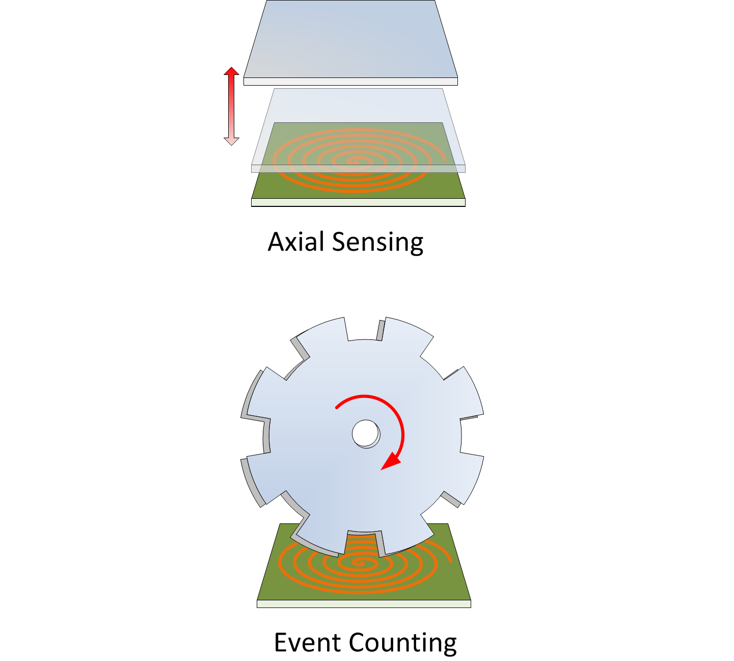
Inductive sensing provides contact-less sensing of conductive objects using only an AC magnetic field. This approach has many compelling features, including low cost, high reliability, low power consumption, and robust operation even in challenging environments experiencing high temperatures or in the presence of moisture, dirt, or oil. In addition, TI’s LDC devices do not require permanent magnets, and are not affected by permanent magnets. LDC technology can measure a wide range of target movement configurations, as shown in Figure 1-1.
GUID-22D56E97-A739-4660-B273-553CBC546F56-low.pngFigure 1-1 LDC Sensing Configurations