SNOA957B September 2016 – June 2021 LDC0851 , LDC1001 , LDC1001-Q1 , LDC1041 , LDC1051 , LDC1101 , LDC1312 , LDC1312-Q1 , LDC1314 , LDC1314-Q1 , LDC1612 , LDC1612-Q1 , LDC1614 , LDC1614-Q1 , LDC2112 , LDC2114 , LDC3114 , LDC3114-Q1
2.3 Sensors Have Two Sides
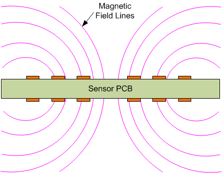
The magnetic field generated by the sensor, is symmetrical above and below the sensor, as shown in Figure 2-7.
 Figure 2-7 Symmetrical Field Lines
Movement of a conductive object on the opposite side of the sensor from the target can interfere with measurement of the target position. There are several methods that can be used to mitigate this effect:
- Move the interferer far enough away from the target that the interferer movement does not affect the target measurement (refer to the Texas Instruments Analog Wire blog post How far can I sense for more information.
- Bring the target closer to the sensor.
- If the interfering conductor is farther away than the target, consider reducing the sensor size (although this can reduce the measurement resolution when the target-to-sensor distance exceeds sensor radius).
- Fix the position of the interferer so that it does not move with respect to the sensor. This approach is effective as long as the loading from the interferer does not exceed the sensor drive.
- Change the material composition of the interferer to larger resistivity such as plastic.
- Use a magnetic shielding material such as a ferrite. This does not reduce the sensitivity to the target, and in some cases can even extend the range slightly – refer to the TI Analog Wire blog post How to shield from metal interference for additional details.
- Use a sheet of metal to shield. This will reduce the measurement accuracy of the target position. A minimum metal sheet thickness of 3 skin depths is recommended to shield from any other conductive objects on the reverse side of the sensor.