SNOAA04A March 2020 – June 2021 FDC1004 , FDC1004-Q1 , FDC2112 , FDC2112-Q1 , FDC2114 , FDC2114-Q1 , FDC2212 , FDC2212-Q1 , FDC2214 , FDC2214-Q1 , LDC0851 , LDC1041 , LDC1051 , LDC1101 , LDC1312 , LDC1312-Q1 , LDC1314 , LDC1314-Q1 , LDC1612 , LDC1612-Q1 , LDC1614 , LDC1614-Q1 , LDC2112 , LDC2114 , LDC3114 , LDC3114-Q1
2 Inductive Sensor Simulation
- Design a coil using the LDC Tools Excel calculator's Spiral Inductor Designer. The dimensions of this coil will be used to create the FEMM simulation. Instructions are embedded in the tool.
- Create a new problem
- Open FEMM
- Click File → New
- In the Create a new problem dialog box, select Magnetics Problem and click OK.
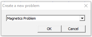 Figure 2-1 Create a New Problem Dialog Box
 - Make the new problem a planar problem or an axisymmetric problem.
When choosing between the two problem types, consider the geometry of the coil. For both planar and axisymmetric problems, the FEMM workspace forms a cross section of the coil and target. The workspace is a slice of the PCB coil such that all layers and traces of the PCB are visible. Keep this in mind while constructing the coil. It is important to construct the cross section such that the simulation will create a coil shape. See how each problem type turns the 2D workspace into a 3D solution:
- Planar problems:
Planar problems expand along the axis perpendicular to the plane. The user must specify the distance of this expansion. This type of problem is most often used to simulate racetrack coils. However, planar problems cut off the rounded edges of the coils, leaving only the long parallel section. This makes the simulation much less accurate than spiral coil simulations using axisymmetric problems.
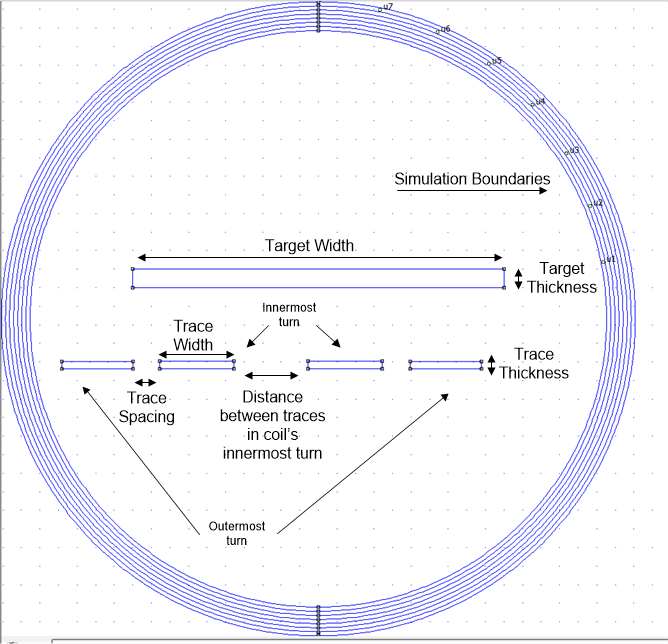 Figure 2-2 Example Planar Problem Workspace With Labeled Traces and Target
 - Axisymmetric problems:
Axisymmetric problems rotate around a user-specified axis. This type of problem is the most useful for inductive sensing simulations and should be used for all circular coils. Note that coils simulated with this problem type will not be true coils, but will be a series of concentric circles. Even so, the coils are fairly accurate simulations.
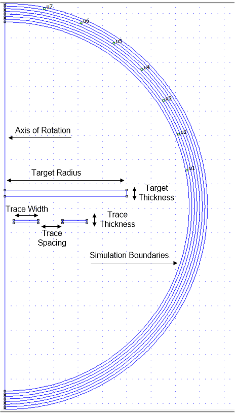 Figure 2-3 Example Axisymmetric Problem Workspace With Labeled Traces and Target
- Planar problems:
- Define the problem.
- Navigate to the Problem menu shown in Figure 2-4.
- In the Problem Definition dialog box, choose planar or axisymmetric for the Problem Type. If “planar” is selected, enter the depth of the problem expansion in the Depth field.
- Enter the appropriate length units for the coil design in the Length Units field. Typically mm or mils are most useful.
- Define a Frequency (Hz). All magnetic problems must have a defined frequency. For inductive sensing problems, this is comparable to choosing a capacitor for a known inductor.
Use the Spiral Inductor Designer in LDC Tools to calculate a frequency and enter that frequency in the problem Frequency (Hz) field. If the FEMM simulation includes a target, use the sensor frequency with target interaction.
- In the AC Solver field, select Succ. Approx. Ignore the other fields and click OK.
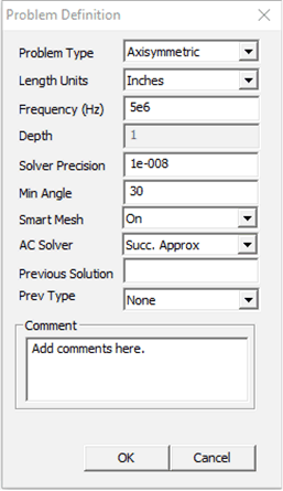 Figure 2-4 Problem Definition Dialogue Box
 - Place nodes
- Use this button
 to place nodes. Use either segments
  or arcs
  to connect them. At least two nodes must be placed before placing segments. These will form the boundaries of your shape(s).
 Use the trace width, trace spacing, and trace thickness from the Spiral Inductor Designer to create a cross section of each trace. Here are key tips for placing objects:
- It can be challenging to place nodes exactly in-line with each other. It may be easier to place one node, copy it, and specify X- and Y- translations for the new nodes. Note that the units are specified in the Problem Definition menu.
- Click close to the desired nodes to place segments or arcs on the node.
- Though the coils in this tutorial will use rectangular traces, the best approximation of real traces is a trapezoidal shape.
- Other helpful tips when moving objects:
- Right-click near an object to select it.
- Double-right-click the object to show the X,Y position of the object.
- Navigate with keyboard arrows.
- Click the Page Up and Page Down keys to zoom in and out.
- Undo only works ONCE.
- Click the
 button to move objects.
 - Click the
 button to copy objects.
 - Click the
 button to select a group of
objects. Then click the
  button to highlight objects in a
rectangular area or the
  button to highlight objects in a
circular area. Press the space bar to join the objects into a
group.
 - Click the
 button to scale
- For axisymmetric problems only: Mouse over the leftmost segment or arc or double-right-click the arc and look at the bottom left corner of the screen to determine the X,Y location of the object. Select all drawn objects and translate them left so that the leftmost segment or arc now has an x-value equal to the inner radius of the sensor coil. The axis of rotation will be the y-axis, so offsets in the x-direction will form gaps or holes in the object.
- Use this button
- Define boundaries
- Click the
 button to open the Boundary Builder.
 - The Boundary Builder builds the model, shows the axis of symmetry, and defines several boundaries that form a gradient to infinity.
- Leave the values in the Open Boundary Builder dialog box unchanged and click OK.
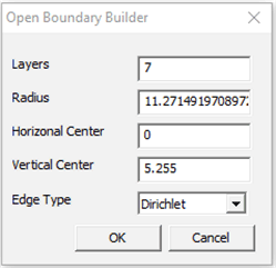 Figure 2-5 Boundary Builder Dialogue Box
 - The workspace should now look similar to Figure 2-6 for axisymmetric problems or similar to Figure 2-7 for planar problems:
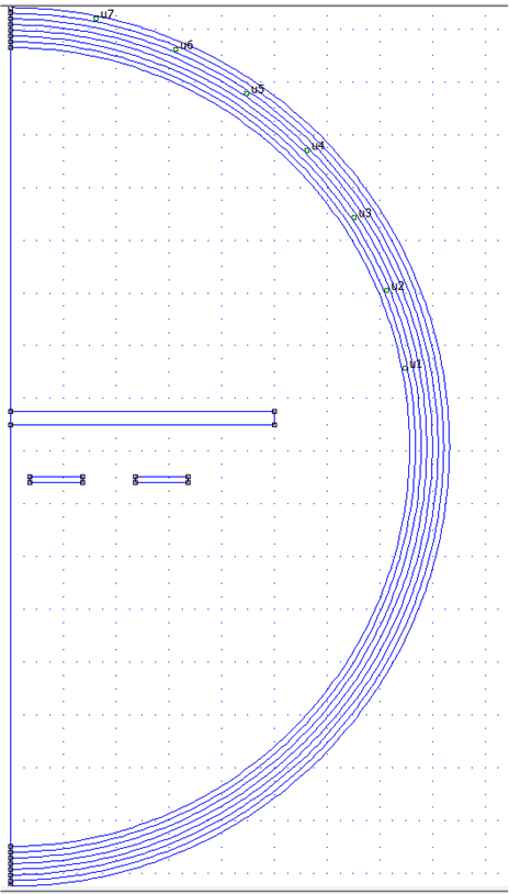 Figure 2-6 Axisymmetric
Problem With Boundaries
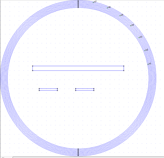 Figure 2-7 Planar Problem
With Boundaries
- Click the
- Define materials
- Select the circular green button
 to place block labels. Place a block label
inside each boundary area, including the white space inside the outer
boundary. The result should look something like Figure 2-8:
 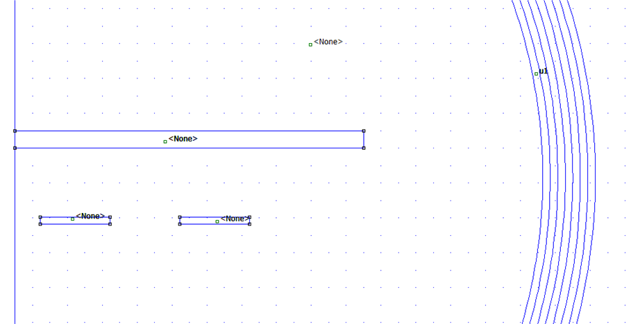 Figure 2-8 Axisymmetric
Problem Workspace With Block Labels
 - Each block label must be changed from <None> to a defined material. First, the materials must be added to the Materials Library. Navigate to Properties → Materials Library.
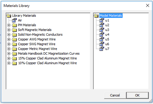 Figure 2-9 Default Materials Library
 - Typically, the engineer only uses air, copper, and the target material if the material is not copper. Drag Air from the left side to the right side of the menu. Open the Solid Non-Magnetic Conductors folder and drag Copper to the right side of the menu. Click OK.
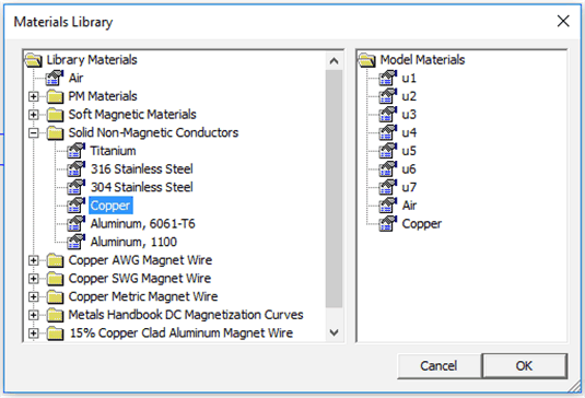 Figure 2-10 Materials Library With Air and Copper Added to Model Materials
 - The copper coil requires a special material type. Navigate to Properties → Materials. In the Property Definition menu, click Add Property to open the Block Property dialog box.
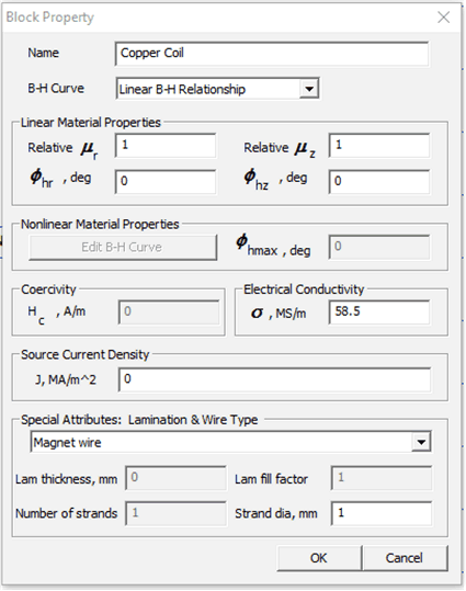 Figure 2-11 Block Properties Menu
 - In the Name field, enter the material name Copper Coil.
- In the B-H Curve drop-down menu, select Linear B-H Relationship.
- The Linear Material Properties do not need to be modified. Copper is a conductor, therefore the material will have a relative permeability of 1.
- Change the Electrical Conductivity field to 58.5 MS/m.
- Change the Special Attributes: Lamination & Wire Type to Magnet wire.
- In the Strand dia, mm field, enter the
strand diameter based on the trace width and copper thickness of
the real coil. Use Equation 1 to calculate the equivalent strand diameter:
- The trace height and width form the cross section of the trace. The area of the equivalent copper wire must equal the cross sectional area of the PCB trace.
- Solve for r in mm. Use 2r for the strand diameter and enter this value in the Strand dia, mm field.
- This calculated diameter does not affect the size of the inductor nor the spacing. This is determined by the boundaries in the workspace. The strand diameter does affect the coil's series resistance.
Equation 1.- T is the trace thickness in mm
- W is the trace width in mm
- r is the strand radius in mm
- Right-click near the material labels to highlight
the names. Press the space bar to open the Properties for selected
block menu. Change the Block type to the appropriate material
for the area. Repeat this for all material labels.
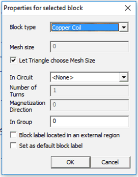 Figure 2-12 Properties for
Selected Block Menu
 - After these steps, the workspace should look
something like Figure 2-13:
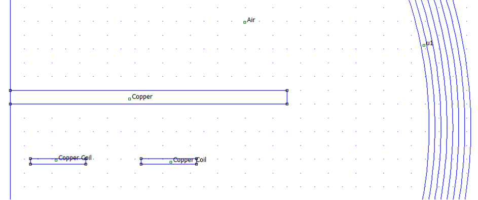 Figure 2-13 Axisymmetric
Problem Workspace With Defined Materials
- Select the circular green button
- Add circuits to the problem
- Navigate to the Properties → Circuits menu. In the Property Definition dialog dox, click Add Property.
- In the Circuit Property dialog box, name the circuit and specify an operating current.
- The current value is not especially important. A value anywhere from 1 mA to 1 A is acceptable.
- Make sure the Series option is checked and click OK.
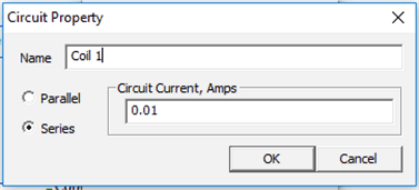 Figure 2-14 Circuit Property Menu
 - For planar problems only:
- For racetrack coils and similar circuits, the parallel traces are not automatically connected by the planar expansion. At least two separate circuits are required to correctly model the current flow.
- To model the current flow, define two circuits with
the same current magnitude. One should be positive and the other
should be negative. Assign one to each side of the racetrack
coil. Your workspace should look similar to Figure 2-15:
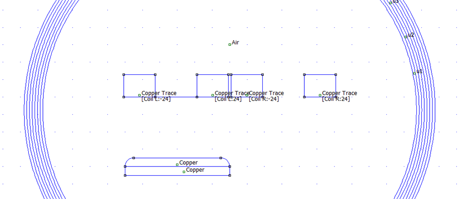 Figure 2-15 Example Planar Problem Workspace With Defined Circuits
for Racetrack Coil
- Right-click the material nodes again and click the space bar to return to the Properties for selected block menu.
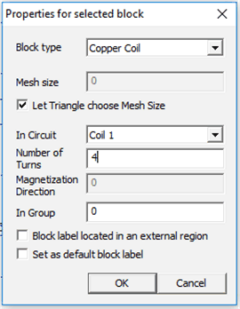 Figure 2-16 Properties for Selected Block Menu
 - Select the circuit that you just created in the In Circuit field.
- Specify the number of turns in the coil. This will not change the size of the coil and only change the generated magnetic field. The simulation will yield the most realistic results if only one turn is used per coil boundary and the number of coil boundaries is equal to the number of turns in the real coil.
- Leave the Let Triangle choose Mesh Size box selected.
- Repeat this process for all boundaries in the coil.
The workspace should now look similar to Figure 2-17:
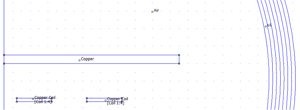 Figure 2-17 Axisymmetric
Problem Workspace With Defined Circuits
- Generate the answer file
- Click the Solve button
 to generate the answer file.
 - Answer files will be saved in the .ans file format in the current working directory.
- Click the Solve button