SNOAA73 May 2021 LMP2012QML-SP , LMP7704-SP , TPS7A4501-SP
Theory of Operation
A 4–20-mA V-to-I current transmitter takes a differential voltage as the input and outputs a current with a linear relationship from input to output. This linear relationship depends on the common-mode range of the op amp and the headroom available for the transistor and LDO. Furthermore, a current transmitter designed with a 2-wire loop requires that the quiescent current drawn from all components on the loop path consume less than the minimum output current Iout_min – 4 mA in this design. This includes the op amp, LDO, the current through the R3 and R5 branch, and any other peripherals that are on the same supply loop. As long as this requirement is met, the op amp and transistor compensate to supply the remaining current to the loop to output the correct current to the load resistor.
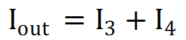
The output current Iout is the sum of the currents through R3 and R4, I3, and I4, respectively:
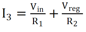
I3 is set by R1 and R2, along with the input voltage Vin and regulated supply Vreg. Under ideal operation, the non-inverting terminal of the op amp has a virtual short to the local ground, Iret. Notice also that Vreg and Vin are referenced to Iret. I3 is then the following:
I4 is the sum of the local ground return current Iret and the compensating current through the transistor T1.
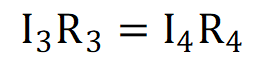
For correct operation of the op amp, the voltages across R3 and R4 must be equal, so we have V3 = V4 and it follows that:
The previous equation is rewritten as:
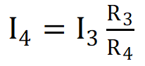
Combining the first equation, second equation, and previous equation, the transfer function for the circuit is derived as:
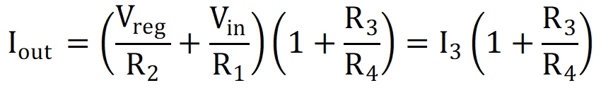
It is apparent, then, that the current
through R3 that is set by R1, R2, Vin,
and Vreg is amplified by the factor
1 +
R3 / R4.