SNOAA87 April 2022 LDC2114 , LDC3114 , LDC3114-Q1
1 Application Brief
Replacing Mechanical Switches With Inductive Sensors
Keypad and push-button applications have long been implemented with mechanical switches that force electrical contacts together and (hopefully) make a low resistance connection.
Dirty environments (for example, grit, oil, and water) can require special housings, gaskets, and other fittings to avoid premature failure. These can in turn fail, causing premature switch malfunction. Robust, sealed mechanical switches that are resistant to contaminants are achievable, albeit at increased cost, and sometimes requiring the use of special materials which can further increase costs.
Variations in switch parameters due to use and environmental factors can cause system failure, or in the very least, place additional burden on the system designer to monitor and replace switches when parameters are outside an acceptable range.
Keypads based on touchscreens can also be prone to failure due to environmental factors like dirt, oil, and other contaminants, dirty fingers, or users wearing gloves.
Inductive Sensing Switches - Overview
Push-button switches based on inductive sensing (LDCs) show very few of these shortcomings. They are robust and not subject to the inevitable failures associated with moving parts and worn contacts due to wear-and-tear from repetitive movement. They can be easily implemented in sealed keypads with no cutouts, immune to contaminants, and maintain reliability even under water. They can accommodate spacious form-factors (to support users with gloves) or small form factors for limited space.
Some devices and designs can also support multi-level push buttons, and some have internal algorithms to manage multiple button-presses as well as mechanical distortions of the case, the keypad, or both, freeing the microcontroller from those functions.
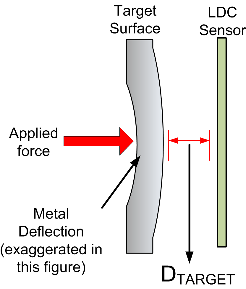
Inductive touch-buttons can be easily implemented with three main components: an inductive sensor, a target surface, and an inductance-to-digital converter (LDC). The sensor can frequently be implemented by a PCB-based or flex-circuit based coil. The target should be a flexible, conductive material, like thin metal with enough thickness to support skin-effect eddy currents.
 Figure 1-1 Inductive Touch Components
When force is applied on the target surface, the material deflects slightly, reducing the distance (DTARGET) between the inductive sensor and the target surface. The deflected conductor reduces the sensor inductance, which in turn causes the sensor resonant frequency to increase which is detected by the LDC. As a target deflection example, a button with a 20-mm diameter will deflect about 0.1 μm if the target material is 430 stainless, 1-mm thick. When the force is removed, the button surface returns to its original shape.
Inductive Sensing Switches - Sensitivity
The primary factors that contribute to the sensitivity of an inductive touch button are the target material and thickness, the target distance, and the sensor size. Button sensitivity is defined in terms of force that needs to be applied on the target conductive surface to trigger the desired LDC response.
Target Material
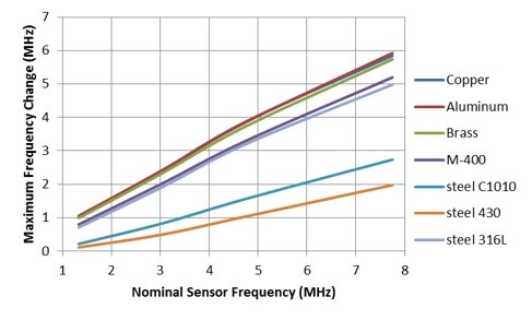
A material with higher electrical conductivity (σ) is a better target for inductive sensing technologies. The amount of eddy currents generated on the target are directly related to conductivity (σ) of the target material. Materials with higher conductivity (such as copper, aluminum, or silver) make better targets for inductive touch buttons. A thin layer of conductive material can be added on to non-conductive materials like plastic to make effective targets for push-button applications. Figure 1-2 illustrates the sensitivity of the LDC to the conductivity of the material via the dependence of the sensor frequency shift (which the LDC detects) on the target material and the sensor frequency (which impacts the skin effect). The LDC Target Design application note provides additional details, and the spreadsheet-based LDC Sensing Design Calculator Tool lets you calculate and model the effects of target conductivity and thickness.
 Figure 1-2 Target-Induced Frequency Shift versus Nominal Sensor Frequency
Deflection produced in the target surface with a given amount of force is inversely proportional to the tensile strength and thickness of the material. A thinner or less rigid material requires less force than a thicker or more rigid one. The previously-mentioned spreadsheet tool allows this to be modeled.
Target Distance (DTARGET) and Sensor Size
As previously mentioned, an inductive sensing switch relies on the interaction of EM fields generated by the inductive sensor. The field lines are directly proportional to the diameter of the sensor and the eddy currents they induce on the target surface decrease as DTARGET increases.
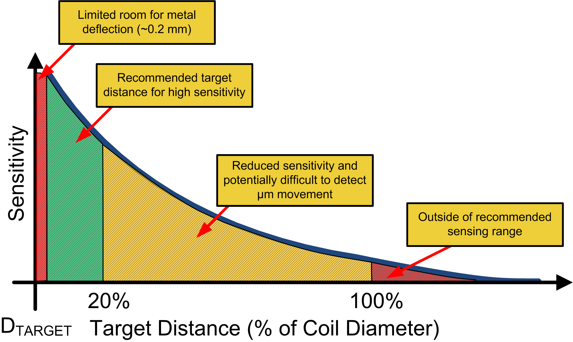
Figure 1-3 illustrates the dependence of switch sensitivity on the target distance as it relates to the sensor diameter. As the diagram shows, the best switch sensitivity happens when the DTARGET is within 20% of the diameter of the sensor coil.
 Figure 1-3 Shows Button Sensitivity as a Function of DTARGET
Button-Oriented Features in High-Resolution LDCs
The high resolution of LDCs allow reliable designs of inductive switches, even when the deflection or movement of the target is small. For example, a small 3-mm by 10-mm button made from 0.2-mm aluminum has 1.9 μm of deflection with 1.5 N of applied force. This relatively small displacement causes a 1000 ppm change in the resonant frequency (or 2000 ppm change in the inductance of the sensor) of the underlying LC circuit, which is easily detectable by a device like the LDC3114.
As previously mentioned, one of the major advantages of LDC-based switches is the ability to easily seal the switch assemblies, making them impervious to humidity, moisture, dirt, and other contaminants. They can also be made robust to mechanical stresses resulting from drops or dents in the switch housing.
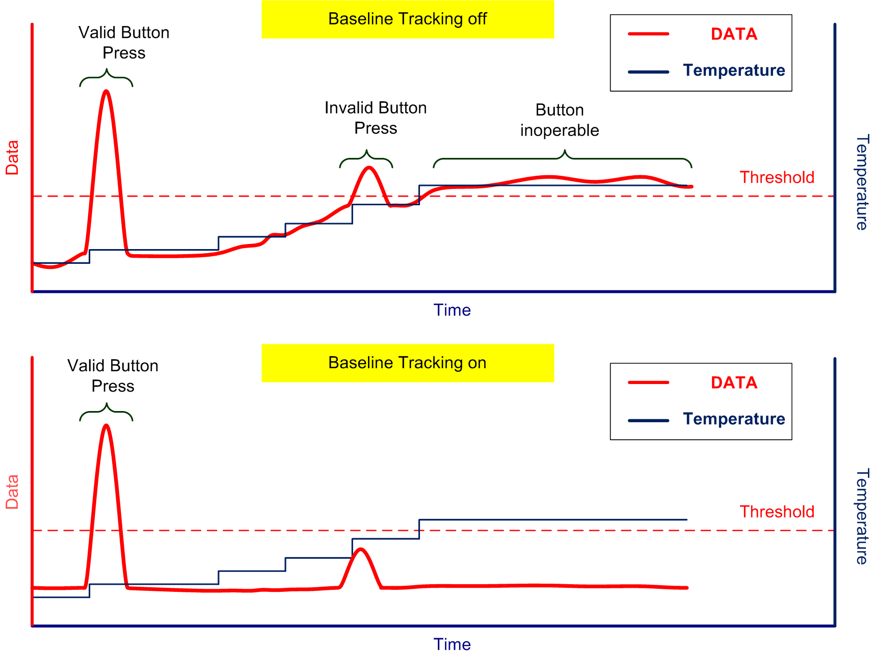
Temperature-based changes in the inductive switch can be accommodated by the baseline tracking algorithm of an LDC, as shown in Figure 1-4. The baseline tracking - for all intents and purposes - results in a high-pass filtered version of the button input signal. The LDC3114 or LDC2114 accomplish this by subtracting a very slowly varying version of the output code (changing over a span of seconds) from the output code driven by the user interaction (over a typical 50-ms time span). For more information, see the respective device data sheets or the LDC211x and LDC3114 Internal Algorithm Functionality application note.
 Figure 1-4 Button Press Responses With Baseline Tracking OFF and ON
The impact of baseline tracking is illustrated by comparing the plots in Figure 1-4. The top plot shows slow variations in the data output - perhaps due to temperature changes – resulting in a false button press. The bottom plot - with baseline tracking active - shows how tracking of the slowly varying output codes are subtracted from the momentary output DATA to prevent the false button press.
The LDC3114 or LDC2114 baseline tracking can be optimized for normal power modes and low power modes via internal register settings.
Button Sensitivity
LDC button sensitivity can be optimized via the 64-level gain factor in the GAINn register of the device. It will enable sensitivity enhancement of individual buttons to ensure consistent behavior between different mechanical structures. The gain required for an application is primarily determined by the mechanical rigidity of each individual button.
Button Triggering Threshold
Every target material shows some hysteresis when the material deforms then returns to the original state. The amount of hysteresis is a function of material properties and physical parameters, such as size and thickness. This feature optimizes the hysteresis of the button signal threshold according to different materials and various button shapes and sizes.
Mitigating False Button Detections
The LDC3114 has digital OUTx pins that indicate button activity independently of the I2C interface, so after initial set-up, the LDC3114 can be made to operate independently of a microcontroller. The LDC3114 or LDC2114 inductive switches support features that mitigate false button detections and multiple button presses without the need for intervention by an external microcontroller. A detailed discussion of these features is found in the LDC211x and LDC3114 Internal Algorithm Functionality application note, and a summary of the feature descriptions follows:
The Anti-Common feature can be enabled on individual buttons to eliminate false detection when a user presses the middle of two or more buttons thereby leading to a common-mode response on multiple buttons.
The Max-Win feature enables the system to select the button pressed with maximum force when multiple buttons are pressed at the same time. A plausible scenario for this could happen when two buttons are physically very close to each other, and pressing one causes a residual reaction on the other. The Max-Win feature can be enabled for individual buttons.
The Anti-Twist algorithm reduces the likelihood of false detection when the case is twisted, which could cause unintended mechanical activation of the buttons, or an opposite reaction in two adjacent buttons. When this algorithm is enabled, detection of button presses is suppressed if the output data on any button is negative by a configurable threshold.
The Anti-Deform function filters changes due to metal deformation in the vicinity of one or more buttons. Such metal deformation can be accidentally caused by pressing a neighboring button that does not have sufficient mechanical isolation.
Conclusion and Device Recommendations
Mechanical switch failures imposed by environmental contaminants and wear-and-tear can be easily overcome by using switches based on inductive sensors. If your system would benefit from low-power, low-voltage, high-resolution inductive switches, the LDC3114 or LDC2114 are the best choice. If higher voltage, lower resolutions switches meet your system requirements, then the LDC161X family of devices could be used as inductive switches as well. For more information, see the Inductive Sensing Touch-On-Metal Buttons Design Guide.
References
- Texas Instruments, Inductive Touch Buttons for HMIs application brief
- Texas Instruments, LDC Target Design application note
- Texas Instruments, Inductive Touch System Design Guide for HMI Button Applications application note
- Texas Instruments, Sensor Design for Inductive Sensing Applications Using LDC application note
- Texas Instruments, Inductive Sensing Touch-On-Metal Buttons Design Guide application note