SWRA726 March 2022 CC1120 , CC1121 , CC1201 , CC1310 , CC1311P3 , CC1311R3 , CC1312PSIP , CC1312R , CC1312R7 , CC1314R10 , CC1350 , CC1352P , CC1352R , CC1354P10 , CC1354R10 , CC2340R5-Q1 , CC2640R2L , CC2651R3 , CC2652P , CC2652P7 , CC2652R , CC2652R7 , CC2652RB , CC2652RSIP , CC3130 , CC3135MOD , CC3230S , CC3235MODAS , CC3235MODASF , CC3235MODSF , CC3235S , WL1801MOD , WL1805MOD , WL1807MOD , WL1831 , WL1831MOD , WL1835MOD , WL1837MOD
- Trademarks
- 1Introduction
- 2Antenna Standing Wave Ratio (SWR) Measurement
- 3Evaluation Board Matching Components Location
- 4Volpert-Smith Chart
- 5868-MHz PCB Helix Antenna Measurement and Matching
- 62.4-GHz PCB Compact Antenna Measurement and Matching
- 7 2.4-GHz PCB Inverted-F Antenna Measurement and Matching
- 8Fast in-circuit or in-device Antenna Verification
- 9Conclusion
8 Fast in-circuit or in-device Antenna Verification
There is a fast method for in-circuit or in-device embedded antenna verification/checking. Users can verify or check if the antenna has desired resonant frequency, matching or bandwidth without any soldering.
For this task a reflectometer (or VNA), flexible high-quality cable, handmade pigtail and standard calibration kit need to be used. An example below made by using the CABAN R60 reflectometer (cable and antenna analyzer) made by PLANAR LLC (or R60 model by Copper Mountain Technologies) and R VNA Software application.
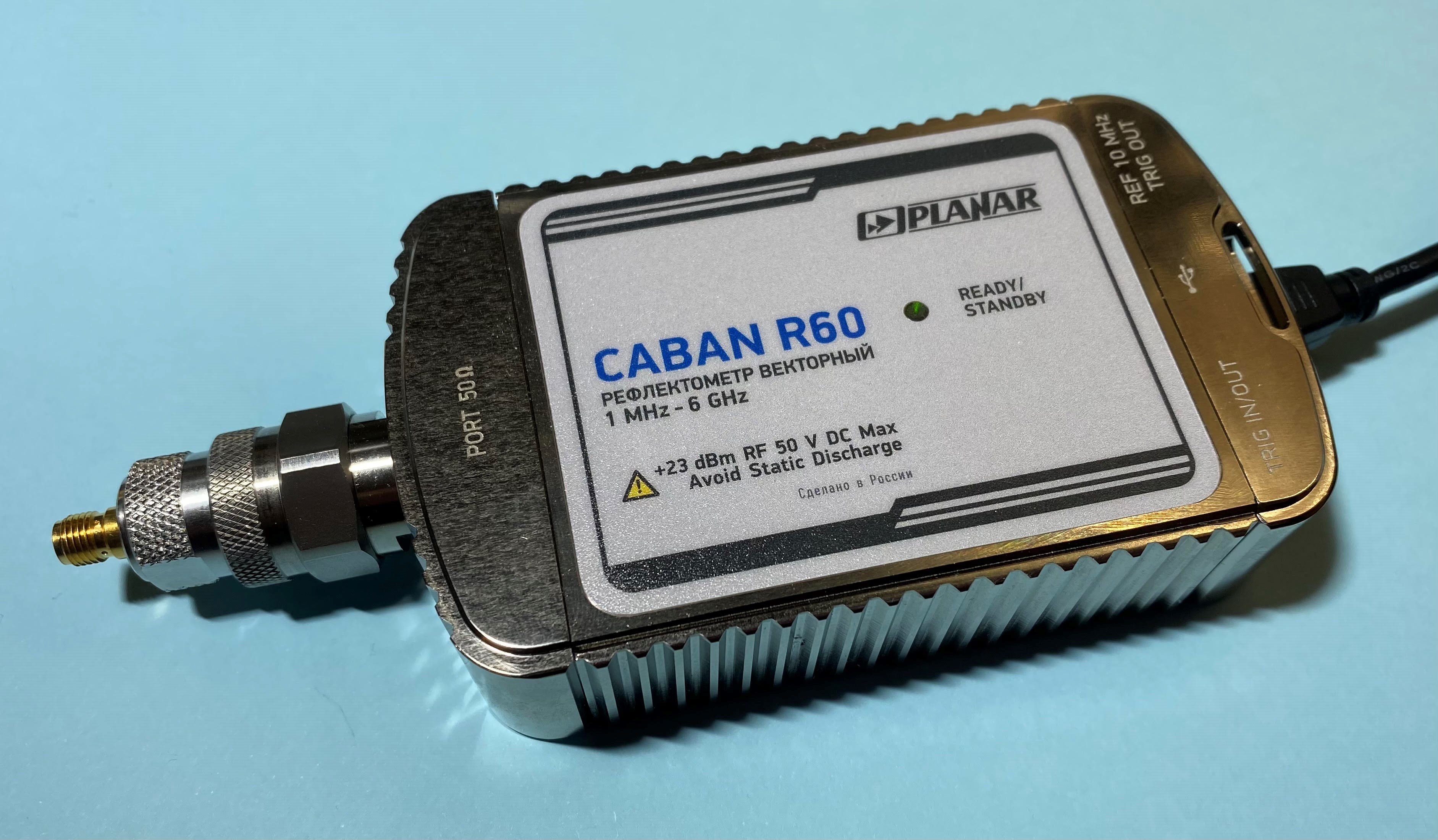 Figure 8-1 Vector Reflectometer CABAN
R60
Figure 8-1 Vector Reflectometer CABAN
R60Small in size and portable reflectometer allows users to test the antenna outside of the lab or in fields. Such cases can be, for example, a smoke detector mounted on a wall, device on a human's body or low power wireless transceiver mounted near metal water pipes (for water/gas meters).
High quality cables are important as measured data will depend on the cable's movement. High quality cables have low instability on movement, so the data will not fluctuate much.
The calibration kit is 03K30R-MSOTS3 by Rosenberger used for calibration.
The pigtail can be made by using a short semi-rigid cable with SMA connector and ground (pogo) pin Figure 8-2. Ground pogo pin can help to get a robust connection and compensate connector’s length mismatch.
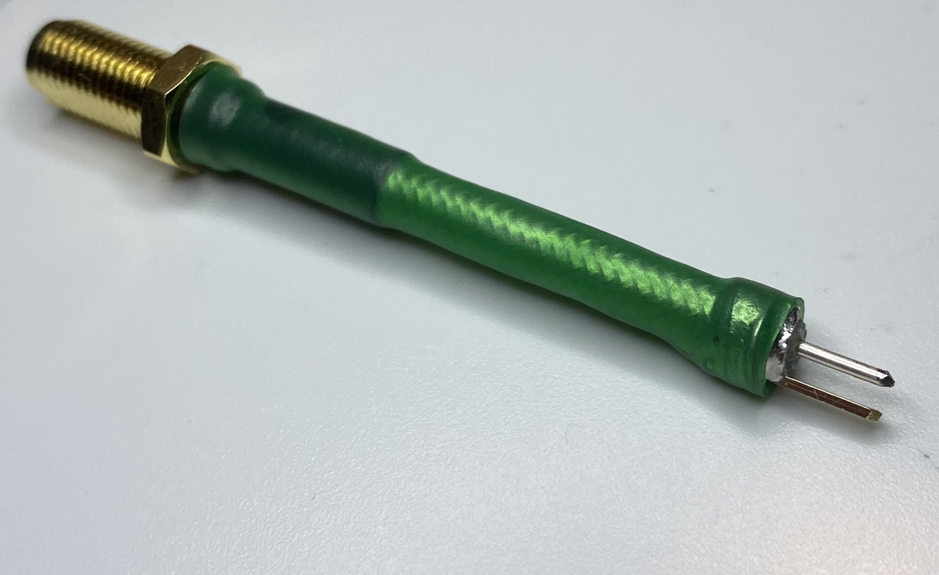 Figure 8-2 Handmade Pigtail
A picture of the setup is shown on Figure 8-3.
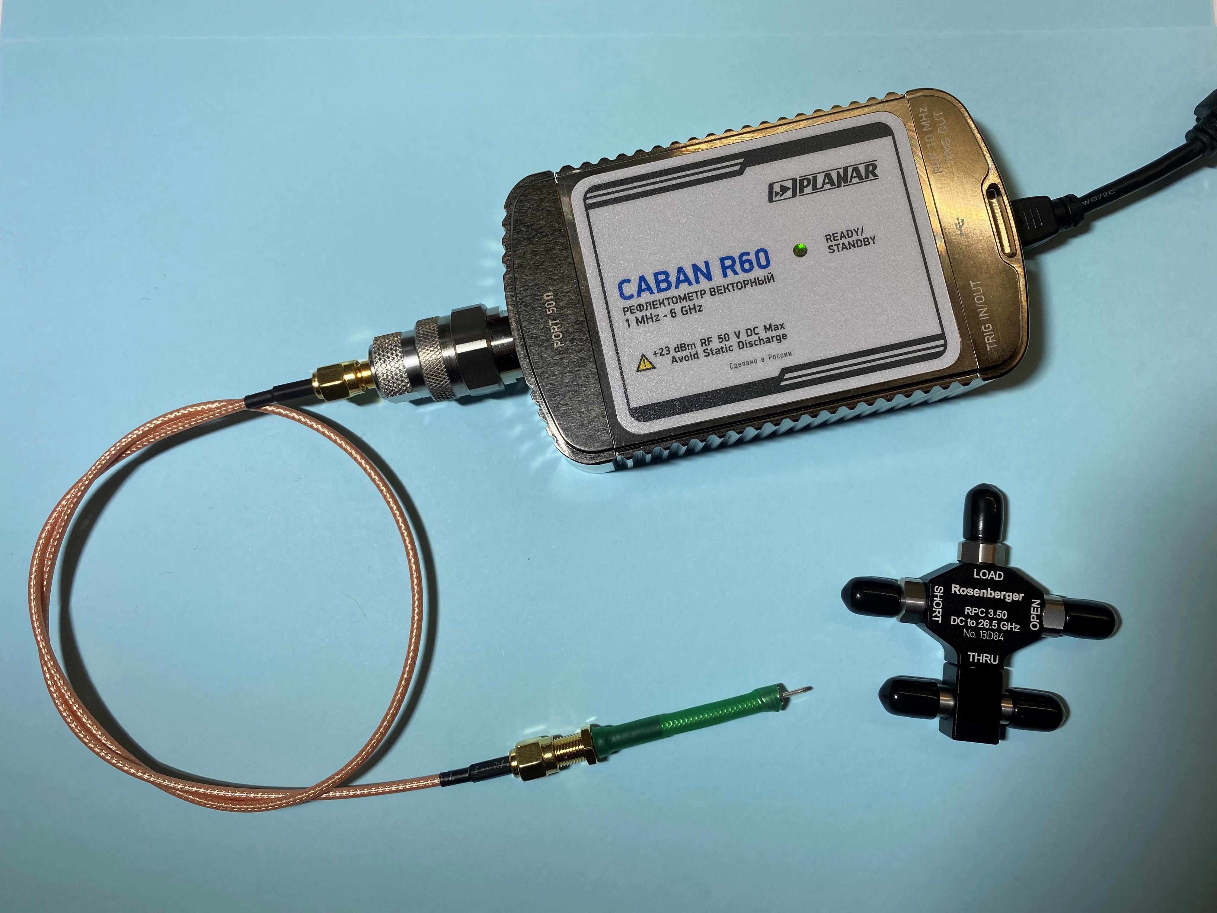 Figure 8-3 Test Setup
Before taking the antenna's measurement, the CABAN R60 vector reflectometer should be calibrated with the standard calibration kit for open, short and matched loads including cable and adapters.
After the calibration users can connect their handmade pigtail to the cable and compensate for phase delay (to move a reference plane) through the port extension option for open load, as the pigtail has opened connectors Figure 8-4.
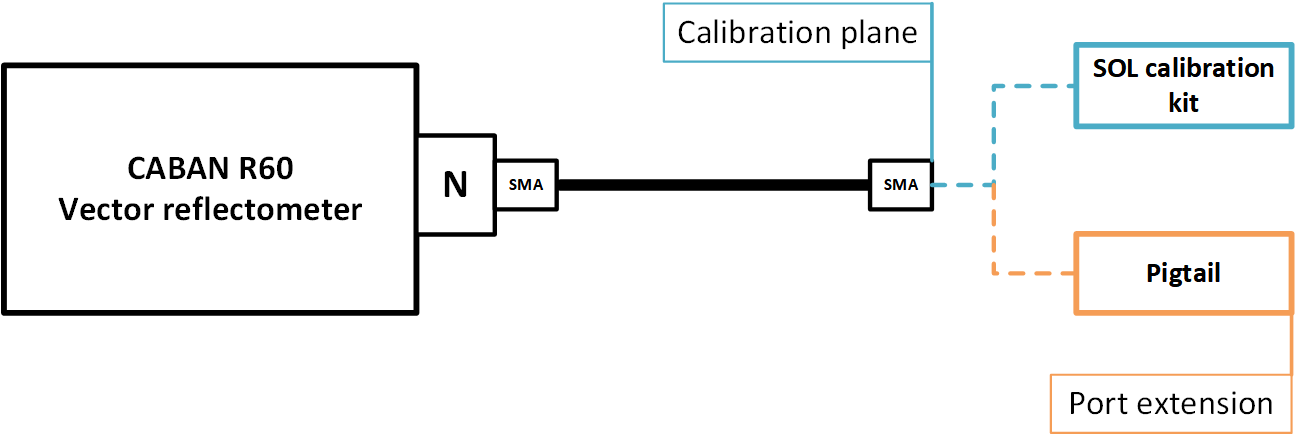 Figure 8-4 Calibration Method Using Port Extension Option
Uncompensated phase delay due to connected pigtail for open load is shown on Figure 8-5.
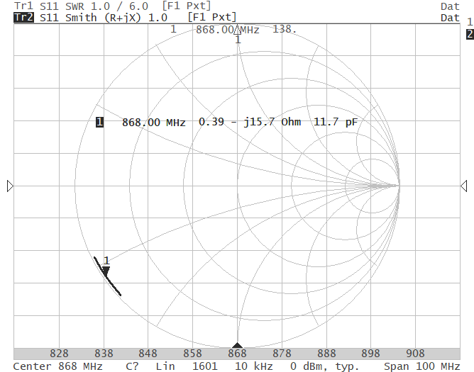 Figure 8-5 Uncompensated Phase Delay After Pigtail Connection
For the port extension option, it’s a good idea to include and compensate a skin effect loss (Include Loss) by switching on a corresponded menu option Figure 8-6.
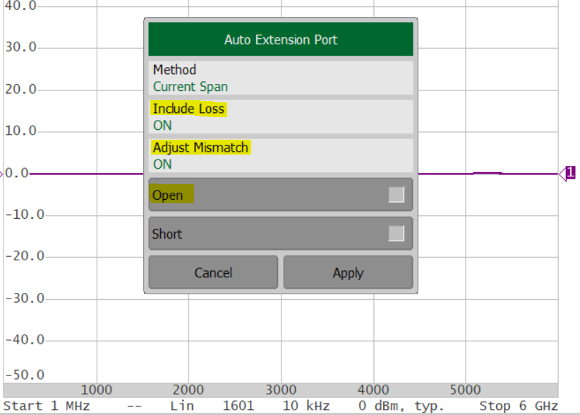 Figure 8-6 Port Extension Option
Compensated delay after the enabled port extension option is shown on Figure 8-7. Phase compensation allows the impedance to be measured correctly.
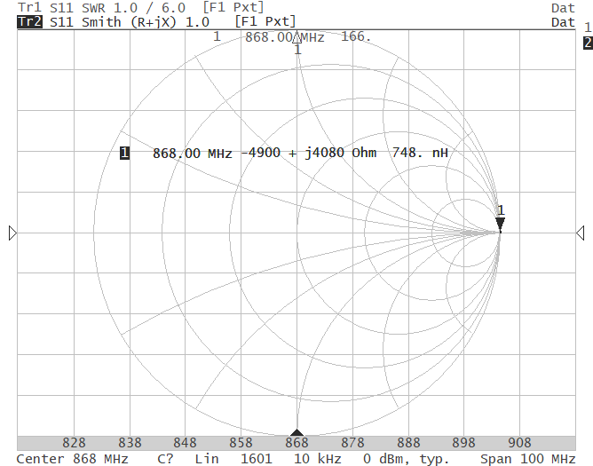 Figure 8-7 Compensated Phase Delay For The Connected Pigtail
Below is an example of measured SWR of an 868-MHz antenna for the same operation conditions made by a connected cable (gray curve) and a connected pigtail (black curve). As users can see there is not much difference in measurements Figure 8-8.
A hand in the nearest zone with the antenna detunes her a little, but anyway allows to check the antenna's resonant frequency and SWR value without any soldering.
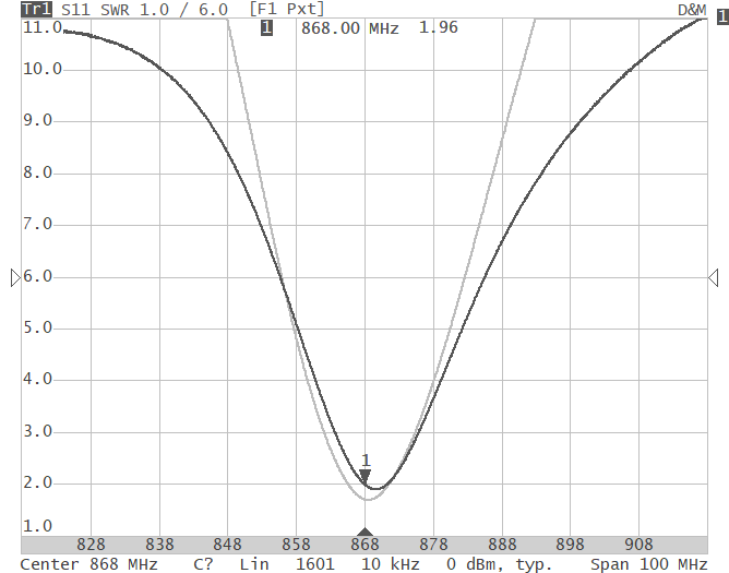 Figure 8-8 Measured Resonant Frequencies and SWR Levels