TIDT256A March   2022  – March 2022


  1.   Description
  2.   Features
  3.   Applications
  4. 1Test Prerequisites
    1. 1.1 LM5156-Q1
      1. 1.1.1 Loading LM5156-Q1
      2. 1.1.2 LM5156-Q1 SEPIC Bode Loop Testing
    2. 1.2 Loading UCC14240-Q1
    3. 1.3 UCC5870-Q1 and UCC5870-Q1 EVM GUI
    4. 1.4 Voltage and Current Requirements
    5. 1.5 Required Equipment
    6. 1.6 Considerations
    7. 1.7 Dimensions
  5. 2Testing and Results
    1. 2.1 SEPIC Efficiency Graphs
    2. 2.2 SEPIC Efficiency Data
    3. 2.3 SEPIC Bode Plots
    4. 2.4 Thermal Images
  6. 3Waveforms
    1. 3.1 SEPIC Switching
    2. 3.2 SEPIC Output Voltage Ripple
    3. 3.3 SEPIC Load Transients
    4. 3.4 SEPIC Start-Up Sequence
    5. 3.5 Isolated Bias Supply Start Up and Shutdown
    6. 3.6 Isolated Gate Drive

Thermal Images

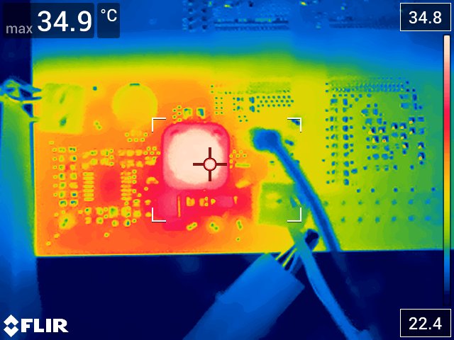
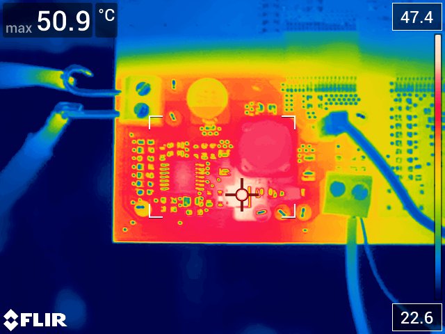
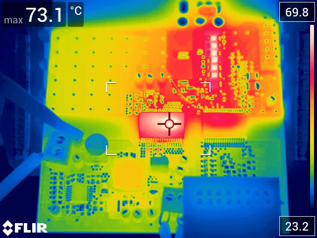
Thermal images are shown in the following figures.
GUID-20220126-SS0I-PH8W-PQFF-PZ4QDFJW2NMN-low.jpg
VIN = 18 VIN, VOUT = 24 VOUT at 130 mA
The SEPIC inductor is the hottest item.
Figure 2-7 SEPIC Thermals at 445-kHz Switching Frequency
GUID-20220126-SS0I-B6NK-L3D4-WF03JBKQRT4W-low.jpg
VIN = 18V, VOUT = 24 VOUT at 130 mA
The SEPIC switch is the hottest item.
Figure 2-8 SEPIC Thermals at 2-MHz Switching Frequency
GUID-20220322-SS0I-QBND-NGN0-VBNHRNLRZQGW-low.jpg
12 VIN to SEPIC, 24 V from SEPIC, +15 V, –5 V from isolated DC/DC. Isolated driver run at 40 kHz, 50% duty into 0.1-μF load for 2 μC per cycle or 80 mA, 1.6-W average current, power draw from isolated DC/DC. Ambient 21°C to 23°C with no fan.
Isolated DC/DC at 73°C, gate driver at 56°C and gate drive resistors up to 76°C
Figure 2-9 Isolated DC/DC and Driver Thermals at 40 kHz, 50% Duty, PWM 100 nF on Gate