TIDU312A May 2014 – November 2020
- Trademarks
- 1Introduction
- 2Software Overview
- 3Procedure for Running the Incremental Builds
- 4Test Results
- 5References
- 6Revision History
3.2.2 Build 2 Overview
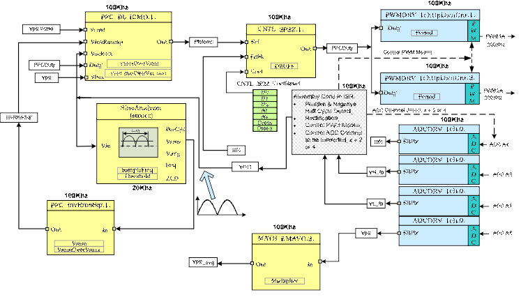
Figure 3-5 shows the software blocks used in this build. Notice that 4 additional software blocks are added to the Build 1 diagram (Figure 3-1) to implement this closed current loop system. The Sine Analyzer block calculates the RMS voltage and frequency of the input voltage. PFC InvRmsSqr block calculates the inverse of the square of the RMS input voltage. This calculated value together with the rectified voltage (Vrect), the sensed DC bus voltage (Vpfc) and PFC PWM duty are used in the 3rd software block PFC_BL_ICMD to generate the reference current command PfcIcmd for the PFC current control loop. PFC_BL_ICMD block uses a 5th input VpfcVcmd for controlling the magnitude of the reference current command. Since this software build implements only the PFC current loop (open voltage loop), this parameter VpfcVcmd needs to be varied from the CCS window in order to adjust the magnitude of the reference current and hence the PFC bus voltage. A two pole two zero (2p2z) controller is used to implement the current control loop. This is the 4th software block shown in Figure 3-5 as CNTL_2P2Z:1. Depending on the control loop requirements other control blocks such as a PI or a 3p3z controller can also be used.
As shown in Figure 3-5 the current loop control block is executed at a 100 KHz rate. CNTL_2P2Z is a 2nd order compensator realized from an IIR filter structure. This function is independent of any peripherals and therefore does not require a CNF function call.
 Figure 3-5 Build 2
Software Blocks
Figure 3-5 Build 2
Software BlocksThis 2p2z controller requires five control coefficients. These coefficients and the clamped output of the controller are stored as the elements of a structure named CNTL_2P2Z_CoefStruct1. The CNTL_2P2Z block can be instantiated multiple times if the system needs multiple loops. Each instance can have separate set of coefficients. The CNTL_2P2Z instance for the current loop uses the coefficients stored as the elements of structure CNTL_2P2Z_CoefStruct1. This way a second instantiation of CNTL_2P2Z with a different structure, CNTL_2P2Z_CoefStruct2, can be used for PFC voltage loop control, as we will see in Build 3, Section 3.3.
The controller coefficients can be changed directly by modifying the values for B0, B1, B2, A1, and A2 inside the structure CNTL_2P2Z_CoefStruct1. Alternately, the 2p2z controller can be expressed in PID form and the coefficients can be changed by changing the PID coefficients. The equations relating the five controller coefficients to the three PID gains are given below. For the current loop these P, I and D coefficients are named as: Pgain_I, Igain_I and Dgain_I respectively. For the voltage loop, used in Build 3, these coefficients are named as: Pgain_V, Igain_V and Dgain_V respectively. These coefficients are used in Q26 format. To change these coefficients from the GUI environment (or from CCS watch views) they are further scaled to values ranging from 0 to 9999.
The compensator block (CNTL_2P2Z) has a reference input and a feedback input. The feedback input labeled as, Fdbk, comes from the ADC. The reference input labeled as, Ref, comes from PFC_BL_ICMD block as mentioned before. The z-domain transfer function for CNTL_2P2Z is given by:

The recursive form of the PID controller is given by the difference equation:

where
-
Equation 3.

And the z-domain transfer function of this PID is:

Comparing this with the general form, we can see that PID is a special case of CNTL_2P2Z control where:

The MATH_EMAVG (Exponential Moving Average) block calculates the average of the output DC bus voltage. The output from this block is used to detect overvoltage condition followed by a PWM shutdown.