TIDUEM8B March 2019 – February 2021
After performing power gain correction, do the phase calibration. Similar to active power gain calibration, to perform phase correction on one phase, the other phase must be disabled. To perform phase correction calibration, complete the following steps:
- If the AC test source has been turned OFF or reconfigured, perform Step 1 through Step 3 from Section 3.2.1.3.2.2.1.1 using the identical voltages and currents used in that section.
- Disable all other phases that are not currently being calibrated by setting the current of these phases to 0 A.
- Modify only the phase-shift to a non-zero value; typically, +60° is chosen. The reference meter now displays a different % error for active power measurement. Note that this value may be negative.
- If the error from Step 3 is not close to zero, or is unacceptable, perform phase correction by following these steps:
- Enter a value as an update for the Phase Correction field for the phase that is being calibrated. Usually, a small ± integer must be entered to bring the error closer to zero. Additionally, for a phase shift greater than 0 (for example: +60°), a positive (negative) error requires a positive (negative) number as correction.
- Click on the Update meter button and monitor the error values on the reference meter.
- If this measurement error (%) is not accurate enough, fine-tune by incrementing or decrementing by a value of 1 based on Step 4a and Step 4b. Note that after a certain point, the fine-tuning only results in the error oscillating on either side of zero. The value that has the smallest absolute error must be selected.
- Change the phase now to −60° and check if this error is still acceptable. Ideally, errors must be symmetric for same phase shift on lag and lead conditions.
After performing phase calibration, calibration is complete for one phase. Gain calibration, offset calibration, and phase calibration must be performed for the other phases.
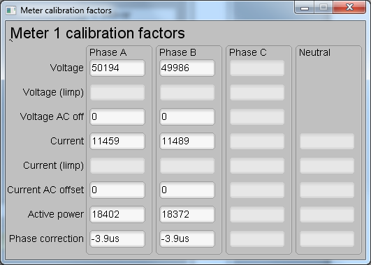
This completes calibration of voltage, current, and power for both phases. View the new calibration factors (see Figure 3-15) by clicking the Meter calibration factors button of the GUI metering results window in Figure 3-12. For these displayed calibration factors, note that the "Voltage AC off" parameter actually represents the active power offset (in units of mW) subtracted from each measurement and the "Current AC offset" parameter actually represents the reactive power offset subtracted (in units of mvar) from reactive power readings. Also, this shows example calibration factors for a meter that uses the two-voltage configuration. If the same meter is set for one-voltage configuration, the voltage and active power scaling factors would be approximately half of what it is in Figure 3-12, since the line-to-line voltage measurement is used for the voltage readings of both phases instead of measuring the two line-to-neutral voltages. Under ideal conditions for a split-phase system, the line-to-line voltage measurement has an RMS value that is twice each of the two line to neutral RMS measurements, which means that the voltage fed to the ADC is also twice as much when measuring line-to-line voltage compared to when measuring line-to-neutral voltage. As a result, for one-voltage configurations, the voltage and power readings have to be divided by an additional factor of two, which is automatically done by following the active power and voltage gain calibration steps.
 Figure 3-15 Calibration Factors Window
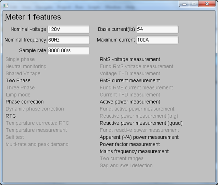
View the configuration of the system by clicking on the Meter features button in Figure 3-12 to get to the window that Figure 3-16 shows.
 Figure 3-16 Meter Features Window