TIDUEM8B March   2019  – February 2021


  1.   1
  2.   2
  3.   3
  4.   4
  5.   5
  6.   6
    1.     7
      1.      8
      2.      9
    2.     10
  7.   11
    1.     12
    2.     13
      1.      14
      2.      15
      3.      16
      4.      17
      5.      18
      6.      19
      7.      20
      8.      21
      9.      22
      10.      23
    3.     24
      1.      25
        1.       26
        2.       27
        3.       28
        4.       29
          1.        30
          2.        31
      2.      32
        1.       33
          1.        34
          2.        35
          3.        36
          4.        37
          5.        38
          6.        39
          7.        40
        2.       41
          1.        42
        3.       43
          1.        44
            1.         45
            2.         46
          2.        47
          3.        48
  8.   49
    1.     50
      1.      51
      2.      52
        1.       53
          1.        54
          2.        55
        2.       56
      3.      57
    2.     58
      1.      59
        1.       60
        2.       61
        3.       62
          1.        63
          2.        64
            1.         65
            2.         66
              1.          67
                1.           68
                2.           69
              2.          70
              3.          71
      2.      72
        1.       73
        2.       74
  9.   75
    1.     76
    2.     77
    3.     78
      1.      79
    4.     80
    5.     81
    6.     82
  10.   83
    1.     84
  11.   85
  12.   86
LCD Controller

The LCD controller on the MSP432P4111 MCU can support up to 8-MUX displays and 320 segments or 4-MUX displays and 176 segment displays. In the current design, the LCD controller is configured to work in 4-MUX mode using 144 segments. The eight segment lines not used in the 4-MUX mode of this design are used for the port mapping functionality. In this reference design, the LCD is configured for a refresh rate set to ACLK / 64, which is 512 Hz. For contrast control, external resistors are added between the R23, R13, R03 pins and GND, as Figure 2-7 shows.
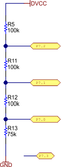
GUID-E6714555-6A2C-48C4-8E52-60828658B838-low.gifFigure 2-7 LCD External Resistors

If the LCD is not needed and P7.0, P7.1, or P7.2 is to be used for some other functionality, such as communication to an external radio module, remove the resistors in Figure 2-7 and use software to implement the desired custom functionality.