TIDUEM8B March 2019 – February 2021
3.1.2.1.2 One-Voltage Connections
AC voltages and currents can be applied to the board for testing purposes at these points:
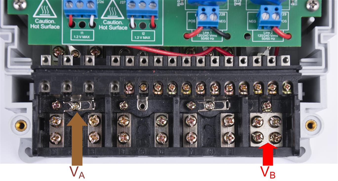
- Terminal block "J28" corresponds to the line voltage connection. This terminal block is a two-position terminal block that has connections for line A and line B. The terminal block position on the left, which is labeled "POS", is where line A is connected. The terminal block position on the right, which is labeled "NEG", is where line B is connected.
- Terminal block "J29" does not need to be used for this one-voltage configuration.
- Terminal block "J26" corresponds to the current inputs after the sensors for line A. This terminal block is a three-position terminal block but only the leftmost and rightmost positions are used. The center position, which is connected to GND, is not connected to the CT. Connect the positive terminal of the CT to the terminal block position on the most left, which is labeled "POS". Connect the negative terminal of the CT to the terminal block position on the most right, which is labeled "NEG". Select the applied current to the input of the CT so that it does not exceed 100 A. In addition, before performing any test, verify that this terminal block is securely connected to both output leads of the CT. Note that the order of the CT leads is reversed here compared to the order on "J27".
- Terminal block "J27" corresponds to the current inputs after the sensors for line B. This terminal block is a three-position terminal block but only the leftmost and rightmost positions are used. The center position, which is connected to GND, is not connected to the CT. The terminal block position on the most right, which is labeled "POS", is where the positive terminal of the CT should be connected. Connect the negative terminal of the CT to the terminal block position on the most left, which is labeled "NEG". Select the applied current to the input of the CT so that it does not exceed 100 A. In addition, before performing any test, verify that this terminal block is securely connected to both output leads of the CT. Note that the order of the CT leads is reversed here compared to the order on "J26".
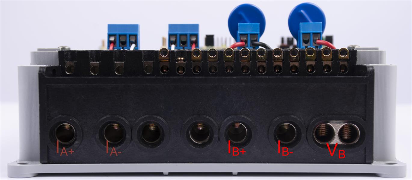
Figure 3-5 and Figure 3-6 show the various test setup connections required for the reference design to function properly for the one-voltage configuration.
 Figure 3-5 Top View
of Reference Design With Test Setup Connections, One-Voltage
Configuration
Figure 3-5 Top View
of Reference Design With Test Setup Connections, One-Voltage
ConfigurationFigure 3-6 shows the connections from the front view. VA and VB correspond to line A and line B. IA+ and IA− correspond to the current inputs for line A while IB+, and IB− correspond to the current inputs for line B.
 Figure 3-6 Front
View of Reference Design With Test Setup Connections, One-Voltage
Configuration