TIDUEM8B March 2019 – February 2021
2.2.1 ADS131M04
The ADS131M04 device is a four-channel, simultaneously-sampling, 24-bit, 2nd order delta-sigma (ΔΣ), analog-to-digital converter (ADC) that offers wide dynamic range, and internal calibration features making it well-suited for energy metering, power quality, and protection applications. The ADC inputs can be directly interfaced to a resistor-divider network, a transformer to measure voltage or current, or a Rogowski coil to measure current.
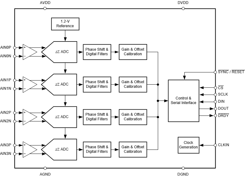
The individual ADC channels can be independently configured depending on the sensor input. A low noise, programmable gain amplifier (PGA) provides gains ranging from 1 to 128 to amplify low-level signals. Additionally, these devices integrate channel to channel phase alignment and offset and gain calibration registers to help remove signal chain errors. A low-drift, 1.2-V reference is integrated into the device reducing printed circuit board (PCB) area. Cyclic redundancy check (CRC) options can be individually enabled on the data input, data output and register map to ensure communication integrity. Figure 2-3 shows a block diagram of this device.
 Figure 2-3 ADS131M04 Functional Block Diagram
In Figure 2-3, 2.7 V–3.6 V must be fed between AVDD and AGND as well as between DVDD and GND. In addition, an external clock must be connected to CLKIN. When the ADS131M04 device is configured for high-resolution mode, this clock must be between 1 MHz and 8.3 MHz for the ADS131M04 to properly work. The CLKIN clock of the ADS131M04 device can be generated from the SMCLK clock output of the MSP432 MCU. The ADS131M04 divides this clock by two and uses this divided clock for its delta-sigma modulator clock. When new ADC samples are ready, the ADS131M04 asserts its DRDY pin to alert the host MCU that there are new ADC samples that are available. Since the ADS131M04 device can accept a clock with a wide frequency range, the device itself can also be used for applications that require coherent sampling.