TIDUEU6B September   2020  – December 2021 OPA810


  1.   Description
  2.   Resources
  3.   Features
  4.   Applications
  5.   5
  6. 1System Description
    1. 1.1 Key System Specifications
  7. 2System Overview
    1. 2.1 Block Diagram
    2. 2.2 Highlighted Products
      1. 2.2.1 OPA2810
      2. 2.2.2 BUF634A
    3. 2.3 Design Considerations
      1. 2.3.1 Existing architecture
        1. 2.3.1.1 Circuit Stability Issue
        2. 2.3.1.2 Solution in Existing Architecture (Compensation Cap)
      2. 2.3.2 Proposed Design
        1. 2.3.2.1 Stability Analysis of the Proposed Design
          1. 2.3.2.1.1 Without Measurement of Voltage at Inverting Node of A2
          2. 2.3.2.1.2 With Measuring Voltage at Inverting Node of A2
        2. 2.3.2.2 RG = RF Settings and Respective Impedance Ranges
        3. 2.3.2.3 Impedance Measurement Procedure
          1. 2.3.2.3.1 Short Cal
          2. 2.3.2.3.2 Impedance Cal
          3. 2.3.2.3.3 100k Setting Calibration
          4. 2.3.2.3.4 Open Cal
          5. 2.3.2.3.5 Calculations
          6. 2.3.2.3.6 Correction in ZX
          7. 2.3.2.3.7 Data Acquisition and Processing
          8. 2.3.2.3.8 Mathematical Explanation
  8. 3Hardware, Software, Testing Requirements, and Test Results
    1. 3.1 Required Hardware and Software
      1. 3.1.1 Hardware
    2. 3.2 Testing and Results
      1. 3.2.1 Test Setup
      2. 3.2.2 Test Results
  9. 4Design Files
    1. 4.1 Schematics
    2. 4.2 Bill of Materials
    3. 4.3 PCB Layout Recommendations
      1. 4.3.1 Layout Prints
    4. 4.4 Altium Project
    5. 4.5 Gerber Files
    6. 4.6 Assembly Drawings
  10. 5Software Files
  11. 6Related Documentation
    1. 6.1 Trademarks
    2. 6.2 Third-Party Products Disclaimer
  12. 7Revision History
Without Measurement of Voltage at Inverting Node of A2

In this method of measurement, the inverting node of A2 is not measured. The assumption behind this method is that the inverting node of A2 is 0V since it is equal to the non-inverting node. This case is only possible in the ideal scenario where the Aol of A2 is infinity. But due to the finite open loop gain of op amp there will always be some small voltage at the inverting node of A2. This voltage is inversely proportional to Aol. As practical op amps have gain decay with respect to frequency, Aol will decrease significantly as the frequency increases. It makes this method of measurement erroneous at high frequencies. Hence the Aol of the amplifier plays a very crucial role in this method of measurement and should be as high as possible. Figure 2-9 explains this method of measurement.
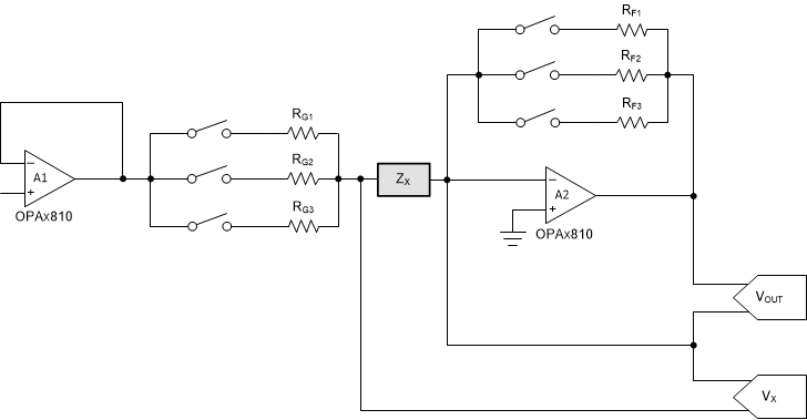
GUID-20200717-CA0I-F7WK-LWK9-3C2QKBK283LK-low.gif Figure 2-9 Method 1 of Impedance Measurement

As this method measures both voltages with respect to ground, data can be acquired using a single-ended ADC.