TIDUEY0 November   2020


  1.   Description
  2.   Resources
  3.   Features
  4.   Applications
  5.   5
  6. 1System Description
    1. 1.1 Li-ion Battery Formation
    2. 1.2 Key System Specifications
  7. 2System Overview
    1. 2.1 Block Diagram
    2. 2.2 Design Considerations
      1. 2.2.1 High-Resolution PWM Generation
      2. 2.2.2 Feedback Controller
      3. 2.2.3 Multiphase Configuration
      4. 2.2.4 Current and Voltage Feedback
      5. 2.2.5 Delta-Sigma ADC Clock Frequency Tuning
      6. 2.2.6 Minimize Crosstalk Error With a Differential ADC
      7. 2.2.7 Overcurrent Protection
    3. 2.3 Highlighted Products
      1. 2.3.1 TMS320F280049
      2. 2.3.2 ADS131M08
      3. 2.3.3 INA821
  8. 3Hardware, Software, Testing Requirements, and Test Results
    1. 3.1 Hardware Requirements
    2. 3.2 Software
    3. 3.3 Test Setup
    4. 3.4 Test Results
      1. 3.4.1 Constant Control Accuracy ADS131M08 Feedback
      2. 3.4.2 Constant Control Accuracy 12-bit ADC Feedback
      3. 3.4.3 Constant-Voltage Control Accuracy
      4. 3.4.4 CC, CV Transformation
      5. 3.4.5 Constant-Current Transient Response
      6. 3.4.6 Charge to Discharge Mode Transition
  9. 4Design and Documentation Support
    1. 4.1 Design Files
      1. 4.1.1 Schematics
      2. 4.1.2 BOM
    2. 4.2 Tools and Software
    3. 4.3 Support Resources
    4. 4.4 Trademarks
  10. 5About the Author

Block Diagram

Figure 2-1 is a block diagram of the reference design. The TMS320F280049 MCU can control up to 8 independent channels. It generates a high-resolution 16-bit PWM for a synchronous buck power stage and performs subroutines for current and voltage control loops. The INA821 instrumentation amplifier senses the current and the TLV07 operational amplifier senses the voltage. Current and voltage signals are converted to digital data by both the external ADS131M08 ADC and the C2000 on-chip ADC. Having the 16-bit ADC in the feedback achieves a control accuracy better than ±0.01%. For cost-optimized systems, you can eliminate the ADS131M08 from the feedback and use the on-chip 12-bit ADC instead to achieve a control accuracy less than ±0.05%. See the Test Results section for more details.
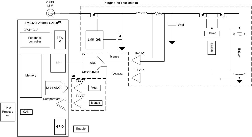
GUID-20201020-CA0I-7B70-DCVN-79P0XSVXHHDT-low.gifFigure 2-1 Digital Control Battery Tester