SBOA347A March 2019 – December 2021 LM7332 , OPA171 , OPA192 , OPA2990 , OPA2991 , OPA2991-Q1 , OPA2992 , OPA4990 , OPA4991 , OPA4991-Q1 , OPA990 , OPA991 , TMS320F28P550SG , TMS320F28P550SJ , TMS320F28P559SG-Q1 , TMS320F28P559SJ-Q1
1 Introduction
High-side current sensing is used in a wide range of applications such as battery chargers or overcurrent protection. Figure 1-1 displays a typical high-side current sensing schematic. The shunt resistor, Rshunt, is placed between the bus voltage and the system load. This creates a differential voltage depending on the load current, which is then amplified to create a single-ended output voltage.
Benefits of High-Side Current Sensing
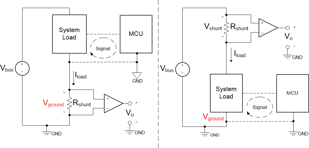
High-side current sensing offers several advantages when compared to low-side current sensing. The first advantage is that high-side current sensing does not create ground disturbances. Ground disturbances are problematic when other circuits in a system are required to interface with the load. Placing the shunt resistor above the load, as in high-side current sensing, eliminates ground disturbances because the shunt resistor is no longer connected directly to ground. Figure 1-2 illustrates the differences in ground potentials between low-side current sensing and high-side current sensing. Notice the voltage potential difference, Vground, between the grounds of the system load and MCU in low-side current sensing, whereas in high-side current sensing, the ground potentials are equal.
 Figure 1-2 Ground Disturbance for
Low-Side (Left) and High-Side (Right) Current Sensing
Figure 1-2 Ground Disturbance for
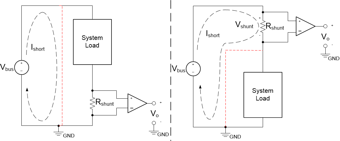
Low-Side (Left) and High-Side (Right) Current SensingA second advantage of high-side current sensing is that it can detect a load short to ground condition. Figure 1-3 displays a load short to ground condition for low-side and high-side current sensing. The red line in the figure indicates the load short to ground current path. Notice that with high-side current sensing, the shunt resistor remains in the circuit and is able to detect a surge in current from a short to ground condition whereas in low-side current sensing, the shunt resistor is removed from the circuit.
 Figure 1-3 Load Short to Ground Condition
for Low-Side (Left) and High-Side (Right) Current Sensing
Figure 1-3 Load Short to Ground Condition
for Low-Side (Left) and High-Side (Right) Current SensingOperational Amplifier Requirements for High-Side Current Sensing
The common mode voltage of the operational amplifier (op amp) must be considered when designing a high-side current sensing circuit. The common mode voltage is set by the bus voltage and the resistor divider formed by resistor R1 and R2, in Figure 1-1, and is calculated using Equation 1.
In high gain applications, such as 100 V/V, the common mode voltage of the op amp must extend to the positive supply of the amplifier. This is because resistor R1 is much greater than R2, making the common mode voltage approximately equal to the bus voltage.
In low gain configurations, such as 10 V/V, the common mode voltage range requirements of the amplifier may not need to extend to the positive supply. In a lower gain configuration, resistors R1 and R2 divide down the bus voltage, which reducing the need for the input common mode voltage to extend all the way to the positive supply. However, using a lower signal gain can require a larger shunt resistor to increase the measured differential voltage, which increases the power dissipation by the shunt resistor.
To ensure accuracy, it is important that R1 and R4 match closely with each other, as well as R2 to R3. Any mismatch can result in gain and CMRR errors. It is recommended to minimize these errors by using precision 0.1% matched resistors for the external circuit.
The input offset voltage also must be considered when determining the solution's accuracy. The input offset voltage is inherent to the op-amp and changes the expected output voltage as shown in Equation 2.
This error can be significant if the offset voltage is near the same value as the voltage across the shunt resistor, Vshunt. Op amps with intrinsically low offset voltages are recommended to minimize the error of the system.
Table 1-1 shows device recommendations with key specifications for high-side current sensing included.
Conclusion
The benefits of high-side current sensing include reducing ground disturbances in a system and detecting fault conditions such as a load short to ground condition. Reducing ground disturbances allows other circuits in a design to interface with each other and ensure proper system functionality. The detection of fault conditions, such as load short to ground, prevents damage or failures of a system. In high-side current sensing, the common mode voltage is dependent on the gain of the circuit and must be considered to ensure proper operation of the circuit.
| GPN | Offset Voltage (typ) | Common Mode Voltage Range | Bandwidth (typ) |
Supply Voltage | Drift (typ) |
|---|---|---|---|---|---|
| OPA2992 | 210 µV | Rail-to-rail | 10.6 MHz | 40 V | 0.25 µV/°C |
| OPA2991 | 125 µV | Rail-to-rail | 4.5 MHz | 40 V | 0.3 µV/°C |
| OPA2990 | 300 µV | Rail-to-rail | 1.1 MHz | 40 V | 0.6 µV/°C |
| OPA2192 | 5 µV | Rail-to-rail | 10 MHz | 36 V | 0.2 µV/°C |
| OPA2191 | 5 µV | Rail-to-rail | 2.5 MHz | 36 V | 0.1 µV/°C |
| LM7332 | 1.6 mV | Rail-to-rail | 21 MHz | 32 V | 2 µV°C |
| Collateral | Link |
|---|---|
| App Report | High-Side Current-Sensing Circuit Design Application Report |
| E-Book | Simplifying Current Sensing |
| Additional Resources | High-side current sensing with discrete difference amplifier circuit |