SLVAEZ1 September 2020 TPS22950
Application Brief
A classic challenge in power distribution is high current events such as capacitive inrush and short-circuit events. These high current events have the potential to damage upstream supplies and downstream loads. In lower power applications, supplies tend to be more restrictive on their power budget.
High-current events in this situation may not cause downstream damage but could pull down the supply voltage which would trigger a undervoltage lockout (UVLO) fault, resulting in the power switch turning off.
Traditionally, load switches solve inrush during turn-on with linear slow rise times. These traditional load switches allow the user to control the rise time with the help of an external capacitor, but the controlled slew rate can only protect the system during startup.
In a situation where a capacitive load is connected after turn on or in a situation where the load fails, high inrush currents can flow unimpeded due to the low on-resistance of the load switch.
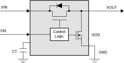
 Figure 1-1 Load switch block diagram
 Integrated load switches establish the power switch foundation by providing safe and reliable distribution of power. When the device is enabled via the ON pin, the pass FET turns on, thereby allowing current to flow from the input pin to the output pin and power is passed to the downstream circuitry.
Load switches offer power distribution systems a small footprint switching solution for on-board power rails that would be difficult to build using discrete components. These devices can be controlled by analog signals or with the help of central MCU.
Current limiting versus short circuit protection in load switches
To overcome the issue of these high current events, there are load switches that offer two distict protection methods; namely short circuit protection (SCP) and current limitng (CL). Short circuit protection is triggered when the device is enabled and the voltage difference between the input and output increases.
When this difference increases above a specified short circuit threshold the device moves into a regulation state. The current limit is triggered when the load current exceeds the internal threshold. A load switch with integrated current limiting has an integrated sense circuit that moves the device into a regulation state.
Short circuit protection and current limiting use different triggers and references to protect against high current events. In both cases the response of the switch is the same. The load switch clamps the current to a fixed value until the device heats up and the die reaches the thermal shutdown threshold and turns off. The switch remains off until the die cools down by a specific amount which is specified in the datasheet and is known as thermal hysteresis.
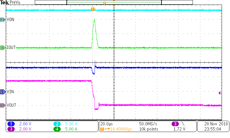
When this cooling threshold is met, the device turns on again assuming that the enable pin has remained high throughout the limiting event. This turn on will be similar to system startup and will use the controlled slew rate feature of the load switch. Some load switches like TPS22919 only offer short to GND protection while other load switches like TPS22948 and TPS22950 offer current limiting.
 Figure 1-2 TPS22919 Short
Circuit Protection with output short to GND
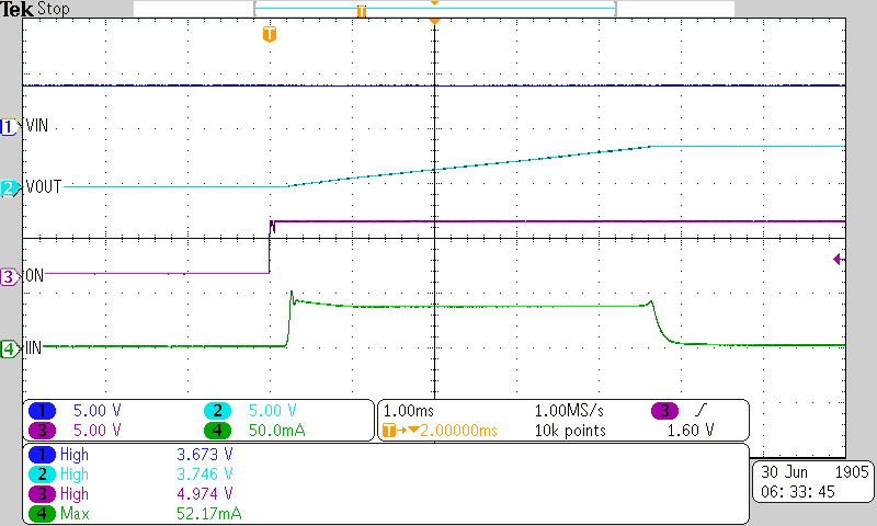
 Figure 1-3 TPS22950 Current Limit during capacitive inrush
Load switches that integrate current limit protection will also protect the system from short circuit events. However, switches that only offer short circuit protection cannot protect the system from mild overcurrent events because the output voltage is not pulled below the protection threshold. When the power budget of the supply is not restricted, short circuit protection is sufficient to protect the downstream loads. When the power budget is restricted as in the case of battery applications, current limiting is preferred as the voltage on the input rail is held stable.
Current limiting in battery powered applications
Portable electrical systems running off battery power benefit greatly from using load switches as these applications are sensitive to quiescent current and thermal efficiency. By using a current limited load switch, these benefits are extended since batteries have a maximum discharge rate and working voltage band making them a power limited sources.
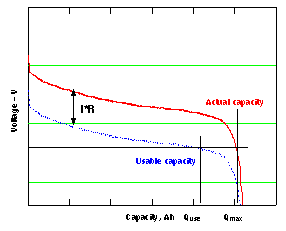
Batteries have a maximum discharge rate (denoted in C) above which the voltage of the battery tends to fall in order to maintain supply. A major concern in battery applications is the minimum allowed discharge voltage of a battery. If the battery is drained under this specified voltage, it can lead to permanent damage. Figure 4 shows the dicharge curve of a single-cell battery under load and the usable capacity. A high discharge event caused during short a short circuit could cause the voltage to dip to unsustaiable levels. Running a battery over the specified maximum discharge rate could damage the battery and should be avoided in most applications.
 Figure 1-4 Discharge Curve of Single-Cell battery
Under Different Load Conditions
Figure 1-4 Discharge Curve of Single-Cell battery
Under Different Load ConditionsIn this situation, a current limited load switch would provide better protection than a load switch only offering short circuit protection. This is because an unsustainable amount of current could instantaneously be pulled from the battery before the difference between input and output voltages rises above the threshold which may result in a heavy voltage drain on the battery. A current limited load switch would start limiting current as soon as the system current exceeds the set limit.
Some load switch families like the TPS2294x devices offer various current limits, response delay times and auto-restart features. The TPS22948 offers a current limit specified for HDMI output port applications. Load switches like TPS22950 can be used to set a user define current limit with an external resistor to ground. With this resistor an internal reference is set that corresponds to the load current flowing through the pass FET. This allows the maximum current to be set to the specifications of the system or in the case of a battery powered system, the maximum allowed discharge rate.
Conclusion
Common design issues for power distribution systems are current overload and short circuit events. By integrating current limiting and short circuit protection into load switches, TI offers small form factor robust switch solutions. These load switch offerings respond quickly to the overload event and either limit the current to allowed levels or turn off the circuit which protects upstream supplies and downstream loads. Reliability of the design is increased by improving efficiency and adding adjustable protection against high current draw events while reducing system level costs.