SLYA046C October 2020 – August 2022 TMAG5123 , TMAG5123-Q1
Application Brief
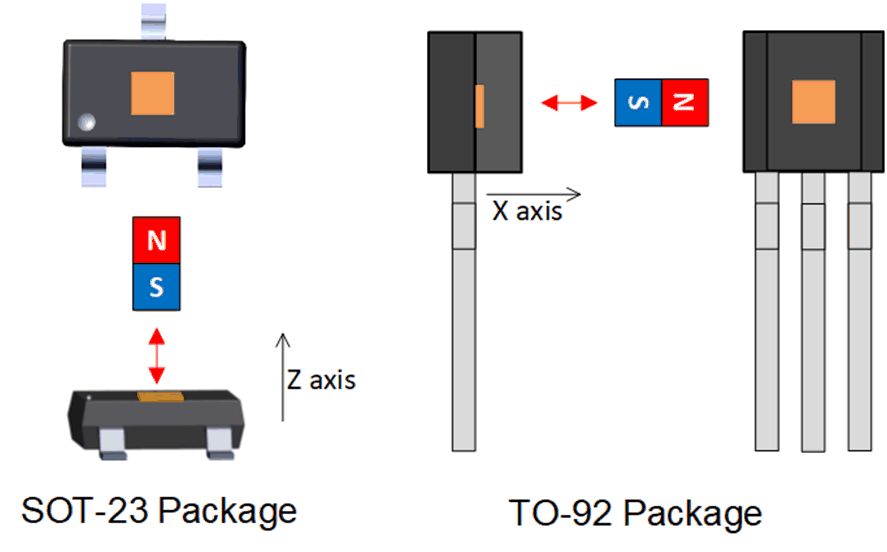
The vast majority of Hall-effect magnetic sensors today—especially if they are single-axis solutions—measure and monitor magnetic fields orthogonally to the surface of the package. As shown in Figure 1-1, the magnetic field of interest would be directed vertically to the sensor in a surface mount package, and the magnetic field would come from a horizontal (or lateral) direction in a through-hole package. In short, most sensors today are sensitive to magnetic fields that are perpendicular to the die within the package.
 Figure 1-1 Most Common Magnetic Field Directionality for Surface Mount (SOT-23) and Through-Hole (TO-92) Packages (Not to Scale)
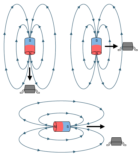
Traditional single-axis sensors are sensitive to magnetic fields from a specific direction, therfore there are correct and incorrect ways of detecting magnetic fields. The illustration in top-left corner of Figure 1-2 shows the SOT-23 package using the traditional method, but there are other ways. The illustration in the top-right corner of Figure 1-2 shows the magnetic field looping back from one pole to another and crossing the sensor orthogonally to the package as expected. For both of these cases, the magnetic flux has the same polarity as the magnet gets closer to the sensor. The bottom image of Figure 1-2 uses the same idea as the previous method, but in a different magnet orientation to the sensor. For this implementation to operate as expected, there must be a vertical offset from the magnet to the sensor to ensure proper magnetic field detection from a Z-axis component. Without this offset, the Hall-effect sensor would only experience horizontal magnetic fields which are undetectable by the sensor. The sensor will also experience a positive and negative magnetic flux density as the magnet traverses across the sensor from one side to the other.
 Figure 1-2 Correct Magnetic Field Detection for
Traditional Sensors
Figure 1-2 Correct Magnetic Field Detection for
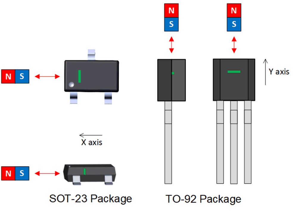
Traditional SensorsTo allow more mechanical variability in system design, Texas Instruments offers a portfolio of in-plane Hall sensors that detect magnetic fields parallel to the surface or horizontally from the side of the package (either X or Y direction) using vertical sensors that are built right into the silicon. Figure 1-3 shows this new in-plane sensing capability.
 Figure 1-3 In-Plane Hall-Effect Magnetic Sensing Solutions
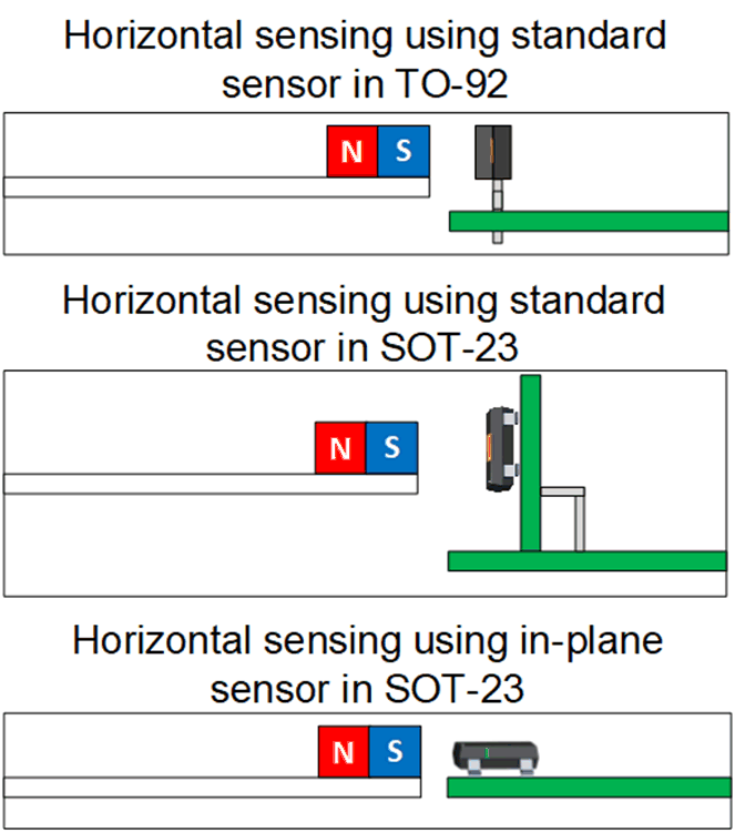
One of the most important benefits of using Hall magnetic sensors with lateral sensing capabilities (such as the TMAG5123 and TMAG5123-Q1) is the flexibility of sensor placement, which can save overall system cost and space. This added capability allows designers to place magnets in orientations not possible with standard orthogonal sensing solutions. For example, the designer may need to place a magnet horizontally in relation to the Hall-effect sensor because the distance in the vertical direction must be kept to a minimum. End products such as vacuum cleaner robots, automotive gear shifters, and home appliances can make use of these added benefits. As shown in Figure 1-4, one solution is to use a Hall-effect sensor in the TO-92 package with standard orthogonal sensing capability. This is a good solution, but designers may want to use a surface mount package for ease of manufacturing. An alternate solution is to build yet another PCB and position it with a surface mount package (SOT-23) to allow the sensor to detect lateral magnetic fields. This particular implementation shown in Figure 1-4 increases cost due to the additional PCB, which increases material costs and could potentially increase the size of system enclosure. The optimal solution also shown in Figure 1-4; however, is the use of an in-plane Hall-effect sensor in the SOT-23 package to reduce the overall space of the package and allow the alignment of the sensor with the magnet.
 Figure 1-4 Various Solutions to Detect Horizontal Magnetic Fields
The capability to sense lateral magnetic fields provides designers yet another option when developing a switch function where other technologies had previously been used. Table 1-1 provides a comparison summary of various technologies to consider.
| TECHNOLOGY | ADVANTAGES, DISADVANTAGES |
|---|---|
| Mechanical switches | Pro: Simple system implementation and can reduce cost in some applications Con: Lower reliability due to mechanical wear and tear; potentially larger solution than with an integrated circuit |
| xMR devices | Pro: xMR sensors are very sensitive and precise and are often low-power Cons: Can be an expensive solution and the availability and options are limited |
| Reed switches | Pro: A proven, low-power solution Con: Yield loss during board placement due to fragility, which may drive system costs up |
| TI In-plane Hall-effect | Pro: Good sensitivity and precision at a competitive price point Con: 15% higher power consumption than Z-axis TI products |
Automotive Applications
In automotive, where many proximity sensing use-cases are needed, in-plane sensing provides added mechanical placement of the magnet. The following are a few applications where such a sensor can be used.
- Braking:
- Brake and clutch pedal switches
- Electronic parking brakes
- Electronic Power Steering (EPS) index sensing
- Hood and trunk latches
- Gear shifter
- Fluid float sensor
- Cabin lighting
Alternate Device Recommendations
Depending on the necessary system requirements, there may be optional devices that provide the needed performance and functionality. For applications where lower power is absolutely necessary but the sensing direction is not as important, the DRV5032 offers a good power-cycled solution available in SOT-23 and TO-92 packages.
Another product to consider is the TMAG5124 that offers the capability to have a very reliable communication between the sensor and the MCU. This product produces a low-level (for output Low) and high-level current output (for output High) depending on the state of the switch. If for some reason the MCU does not sense a current from the Hall-effect sensor, a signal fault can be detected if communication is lost or the sensor is no longer functional. Another huge benefit is the reduction in cabling, as only a single wire is needed between the Hall-effect sensor and the MCU provided that the ground can be terminated locally (such as a chassis ground in a vehicle). Yet another benefit to this device is the ability to transmit signals over longer distances due to the inherent capability of a current-based output that produces lower voltage losses. Table 1-2 shows various Hall-effect sensor options that are alternatives to the TMAG5123 and TMAG5123-Q1.
| DEVICE | OPTIMIZED FEATURE | PERFORMANCE BENEFIT |
|---|---|---|
| DRV5032 | Low bandwidth, low power | Capable for use in battery-operated systems |
| DRV5033 | 2.5-V to 38-V, 30-kHz omnipolar switch | High voltage and high bandwidth |
| TMAG5124 | Current output: 2-mA to 6.9-mA low-level ranges and 12-mA to 17-mA high-level range | Smaller magnets can be used to allow even smaller motor designs |
| DEVICE | SUMMARY |
|---|---|
| Training Videos | Comprehensive training videos on Hall-effect sensors |
| TMAG5123EVM | Socket-based EVM to demonstrate in-plane functionality using the SOT-23 package |