SLUSAL5C December 2012 – June 2016
PRODUCTION DATA.
- 1 Features
- 2 Applications
- 3 Description
- 4 Revision History
- 5 Pin Configuration and Functions
-
6 Specifications
- 6.1 Absolute Maximum Ratings
- 6.2 ESD Ratings
- 6.3 Thermal Information
- 6.4 Recommended Operating Conditions
- 6.5 Supply Current
- 6.6 Digital Input and Output DC Characteristics
- 6.7 Power-on Reset
- 6.8 2.5-V LDO Regulator
- 6.9 Internal Clock Oscillators
- 6.10 ADC (Temperature and Cell Measurement) Characteristics
- 6.11 Integrating ADC (Coulomb Counter) Characteristics
- 6.12 Data Flash Memory Characteristics
- 6.13 I2C-Compatible Interface Communication Timing Characteristics
- 6.14 Typical Characteristics
- 7 Detailed Description
- 8 Application and Implementation
- 9 Power Supply Recommendations
- 10Layout
- 11Device and Documentation Support
- 12Mechanical, Packaging, and Orderable Information
1 Features
- Battery Fuel Gauge and Charger Controller for 1-Cell Li-Ion Applications
- Resides on System Main Board
- Battery Fuel Gauge Based on Patented Impedance
Track™ Technology
- Models the Battery Discharge Curve for Accurate Time-to-Empty Predictions
- Automatically Adjusts for Battery Aging, Battery Self-Discharge, and Temperature/Rate Inefficiencies
- Low-Value Sense Resistor (5 mΩ to 20 mΩ)
- Battery Charger Controller with Customizable Charge Profiles
- Configurable Charge Voltage and Current based on Temperature
- Optional State-Of-Health (SOH) and Multi-Level Based Charge Profiles
- Host Free Autonomous Battery Management System
- Reduced Software Overhead Allows for Easy Portability Across Platforms and Shorter OEM Design Cycles
- Higher Safety and Security
- Run Time Improvements
- Longer Battery Runtime Leveraging Impedance Track Technology
- Tighter Accuracy Controls for Charger Termination
- Improved Recharged Thresholds
- Intelligent Charging—Customized and Adaptive Charging Profiles
- Charger Control Based on SOH
- Temperature Level Charging (TLC)
- Battery Charger Controller for bq2416x Single Cell Switchmode Battery Charger
- Stand-Alone Charging Solution
- 400-kHz I2C™ Interface for Connection to System Microcontroller Port
- In a 15-Pin NanoFree™ Packaging
2 Applications
- Smartphones, Feature Phones, and Tablets
- Digital Still and Video Cameras
- Handheld Terminals
- MP3 or Multimedia Players
3 Description
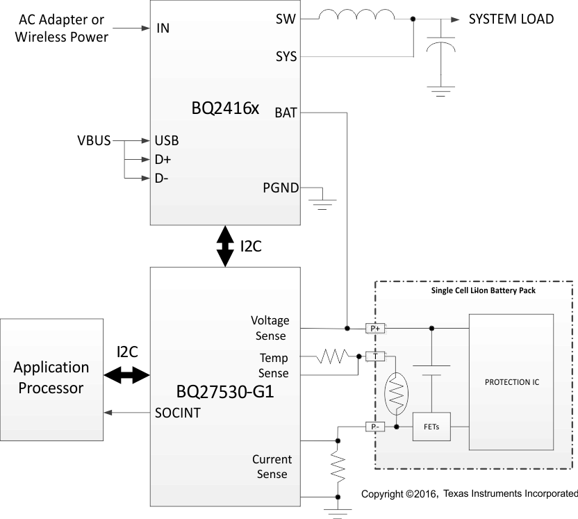
The Texas Instruments bq27530-G1 system-side Li-Ion Battery Management Unit is a microcontroller peripheral that provides Impedance Track™ fuel gauging and charging control for single-cell Li-Ion battery packs. The device requires little system microcontroller firmware development. Together with bq2416x Single-Cell Switchmode Charger, the bq27530-G1 manages an embedded battery (non-removable) or a removable battery pack.
The bq27530-G1 uses the patented Impedance Track™ algorithm for fuel gauging, and provides information such as remaining battery capacity (mAh), state-of-charge (%), runtime-to-empty (min), battery voltage (mV), temperature (°C), and state-of-health (%).
Device Information(1)
| PART NUMBER | PACKAGE | BODY SIZE (NOM) |
|---|---|---|
| bq27530-G1 | DSBGA (15) | 2.61 mm × 1.96 mm |
- For all available packages, see the orderable addendum at the end of the data sheet.
Simplified Schematic
