SBOA163B July 2016 – February 2021 INA225 , INA225-Q1 , INA240 , INA240-Q1 , INA240-SEP , INA280 , INA280-Q1 , INA293 , INA293-Q1 , INA301 , INA301-Q1 , INA302 , INA302-Q1 , INA303 , INA303-Q1
1 Tech Note
High power, precision motor systems commonly require detailed feedback such as speed, torque and position to be sent back to the motor control circuitry to precisely and efficiently control the motor’s operation. Other motor control applications, such as fixed motion tasks, do not require the same level of system complexity to carry out their jobs. Information alerts that the motor had stalled, an unintended object was found in the motor's path, or that a short was detected in the motor's winding can be sent back to the motor control circuitry. More complex motor control systems implementing dynamic control and active monitoring can also benefit from adding simple out-of-range detection function because of the faster indication of out-of-range events.
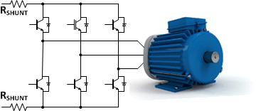
By placing a current sense amplifier in series with the DC power supply driving the high side of the motor drive circuitry as shown in Figure 1-1, the overall current to the motor can be measured easily detecting out-of-range conditions. To detect small leakages the low-side return current can also be measured. A difference between the high-side and low-side current levels indicates a leakage path exists within the motor or motor control circuitry.
 Figure 1-1 Low & High-Side Current Sensing
The DC voltage level varies depending on the voltage rating of the motor leading to multiple current measurement solutions to accommodate the corresponding voltage levels. For low-voltage motors (approximately 5-V), the selection of circuitry to monitor this current is much simpler with multiple amplifier types (current sense, operational, difference, instrumentation) and can perform the current measurement function to support this common-mode input voltage range.
For larger voltage motors (24-V and 48-V, for example), the available options reduces to dedicated current sense and differential amplifiers. As the voltage requirements continue to increase, measurement errors begin to impact the ability to effectively identify out-of-range conditions. One specification that describes an amplifier's effectiveness at operating at high input voltage levels is the common-mode rejection (CMR) term. This specification directly describes how well an amplifier's input circuitry can reject the influence of large input voltages.
Ideally, an amplifier is able to completely reject and cancel out any voltage common to both input pins and amplify only the differential voltage seen between them. However, as the common-mode voltage is increased, leakage currents in the amplifier's input stage result in additional input offset voltage. Larger input range levels being monitored will create proportionally larger measurement errors.
For example, an amplifier (difference amplifier or current sense amplifier) that has a CMR (Common-Mode Rejection) specification of 80 dB will have a significant offset voltage introduced in the measurement based on the input voltage level. An 80-dB CMR specification corresponds to an additional 100 µV of offset voltage induced into the measurement for every volt applied to the input.
Many devices are specified under defined conditions (VCM = 12 V and VS = 5 V, for example) which establishes the base-line for the default specifications (CMR and PSRR, specifically). In this example operating at 60-V common-mode voltage creates a change in VCM of 48 V (60 V – 12 V). A 48-V change with a 80-db CMR results in an additional 4.8 mV of offset voltage in addition to the specified input offset voltage found in the device’s data sheet.
Applications employing calibration schemes are less concerned by this additional induced offset voltage. However, for applications where system calibration cannot account for this shift in offset, selection of an amplifier with better common-mode voltage rejection is required.
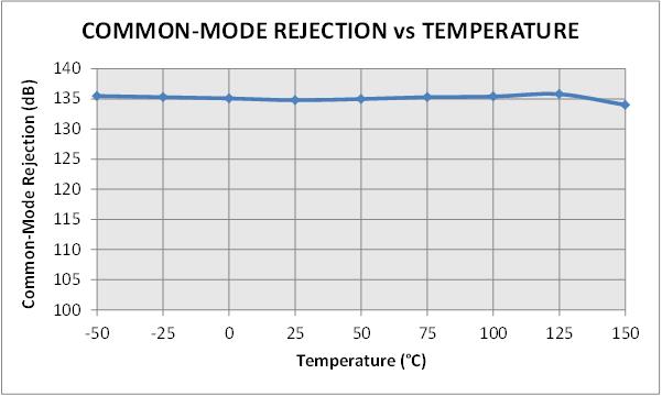
The INA240 is a dedicated current sense amplifier with a common-mode input voltage range of –4 V to +80 V and a worst-case CMR (Common-Mode Rejection) specification of 120 dB over the entire input and temperature range of the device. 120 dB of CMR corresponds to an additional 1 µV of input offset voltage induced for every 1-V change in common-mode voltage. The temperature influence on the amplifier's ability to rejection common-mode voltages is not well documented in many product data sheets so it should be evaluated in addition to the room temperature specification. The INA240 maintains a ensured 120-dB CMR specification over the entire –40°C to +125°C temperature range. The typical CMR performance for the INA240 over the entire temperature range is 135 dB (less than 0.2 µV for every 1-V change) as shown in Figure 1-2.
 Figure 1-2 Common-Mode Rejection vs. Temperature
A system controller has the ability to use the current sense amplifier's measurement to evaluate the operation of the system. Comparing the current information to pre-defined operating threshold allows for detection of out-of-range events. A comparator following the high-side current sense amplifier can easily detect and provide alerts quickly to the system allowing for corrective actions to be taken.
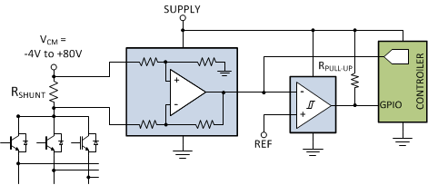
Figure 1-3 illustrates the signal chain path for monitoring and detecting out-of-range excursions when measuring currents on a high-voltage rail driving the motor drive circuitry. The output signal proportional to the measured input current is directed to the ADC in addition to be sent to the comparator to detect overcurrent events. The comparator alert will assert if the input current level exceeds the predefined threshold connected as the comparators reference voltage.
A key requirement for overcurrent detection circuitry is the ability to detect and respond quickly to out-of-range conditions. A fast signal bandwidth device, such as the INA290, enables speedy response to a control unit to ensure other critical system components are not damaged by the unintended excess current flowing in the system. The INA290 is a 1.1-MHz part which can measure on the high-side between 2.7-V to 120-V common mode.
 Figure 1-3 High-Side Overcurrent Detection
Alternate Device Recommendations
If a comparator is required, the INA301 is a good option as it is a precision current sense amplifier with an onboard comparator that is ideal for detecting overcurrent events on common-mode voltages up to 36 V. For applications requiring higher voltage capability, the INA149 is a high performance difference amplifier capable of interfacing with common-mode voltages up to ±275 V off of a ±15-V supply and has a ensured CMR of 90 dB (or 31.6 µV for every 1-V input change). If isolation or high voltage common-mode capability is required, the TMCS1100, hall-effect current sensor, has ±600 V of basic isolation.
| DEVICE | OPTIMIZED PARAMETER | PERFORMANCE TRADE-OFFS |
|---|---|---|
| INA290 | Package: SC-70, Signal Bandwidth (1.1 MHz) | High-side only (2.7 Vcm to 120 Vcm) |
| INA149 | VCM Range: ±275 V | CMR, Gain |
| INA301 | Onboard Comparator; 35 µV VOS | VCM: 0 V to 36 V |
|
±600-V basic isolation |
Not as accurate as a shunt-based solution |
| LITERATURE NUMBER | TITLE |
|---|---|
| SBOA160 | High Precision, Low-Drift In-Line Motor Current Measurements |
| SBOA161 | Low-Drift, Low-Side Current Measurements for Three-Phase Systems |
| SBOA162 | Measuring Current To Detect Out-of-Range Conditions |
| SBOA165 | Precision Current Measurement On High Voltage Power Rail |