SCDA028 September 2020 TMUX1108 , TMUX1511 , TMUX6112
Application Brief
Introductions
A programmable gain amplifier (PGA) is an electronic amplifier whose gain is controlled by a digital or analog signal. PGAs combine two fundamental building blocks of electronics: multiplexers and amplifiers. The most common use cases for PGAs range from data acquisition systems to motor drives. Typically, PGAs are most useful when an input sensor signal needs to vary across different gain values to then be amplified to carry the signal into the next system component. A multiplexer allows for this switching between the different gain values thereby changing the level of amplifications. This document discusses why a multiplexer is used in a PGA, along with the two critical parameters to account for when choosing the right multiplexer for your PGA: on-capacitance (CON) and on-resistance (RON).
Why Select a Multiplexer?
 Figure 1-1 Circuit Model of Basic
Discrete PGA.
 To achieve different gain values, the feedback resistor (Rf) value, see Figure 1, must vary in accordance with the gain needed, as stipulated by Equation 1 of an non-inverting operational amplifier.

This variation can be achieved using a multiplexer. A multiplexer allows for the system designers to switch between different Rf values thereby allowing for multiple gain possibilities. Multiplexers are great cost-effective solutions to use inside PGAs because they come in a variety of configurations while giving the system designer the flexibility in the gain that needs to be achieved.
Low On-Capacitance
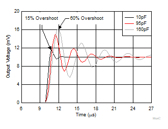
Stability issues can arise from the parasitic on-capacitance interaction with the feedback resistor of the op amp, as Figure 1 shows. The on-capacitance of the multiplexer can cause oscillations in the output signal of the multiplexer, which can negatively impact the integrity of the amplified signal. Therefore, choosing a multiplexer with a low CON, such as the TMUX1511, can help minimize signal distortion and improve the quality and accuracy of the outputted amplifier signal.
For example, a single channel of a 1:1 switch typically has 40 pF of capacitance. Therefore, when all four channels are conducting, the total CON of the feedback path could be 160 pF. However, using a low CON multiplexer, such as the TMUX1511, with 2.5 pF of CON leads to a total feedback capacitance of only 10 pF with all four channels conducting. This significantly lower feedback capacitance ensures that signal oscillations are minimal and the overall impact on the amplified signal is minimal, as Figure 2 illustrates. For more information, see the Improve Stability Issues with Low CON Multiplexers Application Brief.
 Figure 1-2 Op Amp Instability.
 Low On-Resistance
The on-resistance of a multiplexer should be as low as possible to maximize signal integrity through amplification. The higher the RON and the wider the RON flatness range, the more distortion the output signal has due to a higher gain error. The gain error of a multiplexer increases as the RON of the multiplexer increases. For example, the gain error for the circuit in Figure 1 can be calculated using Equation 2.

This gain error calculation assumes a non-inverting circuit and does not account for all other attributes that affect gain error, as it is fundamentally focused on RON. The gain error, as Table 1-1 shows, increases from 0.18% to 10.90% as RON increases from 2 Ω to 120 Ω. Additionally, since Rf is in series with RON, the effects of the changing values of RON are linear, compared to the gain. Finally, in computing the gain error in Table 1-1, an enabled signal path and values of RIN = 100 Ω and Rf = 1 kΩ are assumed.
On-Resistance vs On-Capacitance
There is typically a tradeoff between low RON values versus low CON values. To achieve a low RON, the size of the multiplexer die needs to be wider, so that the current can travel through with minimal interruption. However, as the die size increases, so does the on-capacitance. Low on-capacitance is the result of a smaller distance from source to drain on the multiplexer. Therefore, the system designer must ensure that the optimal multiplexer is chosen for the design taking into account the effects of CON vs RON on the system. The aforementioned TMUX1511 is an example of a multiplexer that has low RON (2 Ω) and low CON (3.3 pF).
Summary
This document discusses why a multiplexer is used in a PGA along with the two critical multiplexer parameters: on-capacitance and on-resistance. Multiplexers are used to switch between different Rf values, which in turn, allows for different gain values for the same op amp. In selecting the right multiplexer, the two critical parameters to watch for are on-capacitance and on-resistance. The lower the on-capacitance, the lower the signal oscillation and distortion, and the more accurate the output signal. Low on-resistance provides a lower gain error and therefore a more accurate signal. Lastly, the system designer must ensure that the optimal multiplexer is chosen for the design taking into account the effects of CON vs RON on the system.
Additional Resources
-
Texas Instruments, TI Precision Labs - Switches and Multiplexers: On-Resistance Flatness and On-Capacitance
-
Texas Instruments, TI Precision Labs - Op Amps: Stability
-
Texas Instruments, Improve Stability Issues with Low CON Multiplexers Application Brief