SLAAE31 September 2021 MSP430F5529
1 Application Brief
USB and UART are common communication interfaces utilized in microcontrollers and when devices need to transfer data across both, a USB-to-UART bridge is constructed. The USB-to-UART bridge acts like a translator between the two interfaces to allow a device to send/receive information on one interface and receive/send the information on the other interface. This document explains the software and hardware solutions used in creating and using the USB-to-UART bridge. The MSP430F5529 microcontroller (MCU) can be used as a solution by providing USB and UART communication interfaces while operating at low power. The accompanying demo uses the MSP430F5529 running at a 24MHz clock speed and 9600 baud rate to demonstrate transceiving data between channels.
Implementation
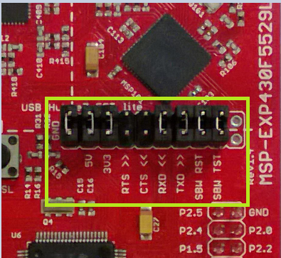
The implementation uses the USB Library provided in the USB Developer's Package Library and the UART Library which uses the UART backchannel in the MSP430F5529. The USB will receive data from the UART and send it to the USB COM port. The UART will receive data from the USB and send it to the UART COM port. The hardware configuration is a USB connection to the PC and the jumper block layout shown in Figure 1-1. The first step to the USB-to-UART bridge is initializing all the required ports and clocks. In this demo, the clock used is the SMCLK at a frequency of 24 MHz. The Hardware Abstraction Layer (HAL) uses the Unified Clock System (UCS), the clock system for the MSP430F5529 device, to initialize the given clock frequency. To increase or decrease the clock speed, just change the value in the USBHAL_initClocks(uint32_t) parameter. The clock ranges from 20 MHz to 25 MHz, so any values lower than that could cause issues when receiving or sending data.
 Figure 1-1 Isolation Jumper Block
A baud rate of 9600 was used in this application; to find the baud rate configuration, the TI Baud Rate Calculator can be used. The USB part of this solution does not need a configured baud rate, so the baud rate configuration can be found in the UART initialization. The ranges for the baud rate are 9600 to 115200, and any other values could cause communication issues when sending or receiving data. The SMCLK is also chosen in the UART initialization, so if a different clock is used, it needs to be changed in the UART.c file as well.
The main purpose of the bridge is a communication path between the two communication interfaces. When receiving data using either UART or USB, it will be stored into the appropriate array. This allows the program to hold the data it is receiving, and then it will send it to the other interface. The process is similar to an echo, but instead of sending the data back to its origin, the data is sent to the other communication interface. The main program loops through an infinite while loop and checks if there is data received on the UART or USB. When data is received, it is stored into a buffer array and then sent to the other communication interface. This process continues until the user forces the program to end or disconnects the USB.
Included UART Library
The UART library was created to group all the UART functions in their own files. The UART.h file contains defined constants for the baud rate registers and can be changed to change the baud rate. The receive buffer size is configured here and can be adjusted to be larger or smaller to transfer different data amounts. A wake threshold variable is also defined here, increasing the threshhold will increase the number of bytes needed to receive before waking up main(). To calculate baud rate go to the Baud Rate Calculator or check the MSP430F5529 Family User's Guide for further baud rate information.
| Constant | Definition |
|---|---|
| UCA1_OS | Oversampling constant; 0 = No oversampling, 1 = Oversampling |
| UCA1_BRx | Clock prescalar |
| UCA1_BRF | First mod register |
| UCA1_BRS | Second mod register |
| BC_RXBUF_SIZE | Set the size of the buffer that receives data across the UART |
| BC_RX_WAKE_THRESH | Threshold value that is set to wake the main application |
The C file for the UART contains all the functions that the UART part of the bridge will use. This file also contains the interrupt service routine (ISR) for the UART interrupts. The main purpose of the interrupt is to receive and store the data from the UCA1RXBUF into a separate array so it can be used later. If a clock other than the SMCLK is needed, then the clock can be changed in the UartInit() function.
| Function | Definition |
|---|---|
| void UartInit(void) | Call once to initialize the UART. Sets TXD/RXD ports, clock type, baud rate, and enables interrupts. |
| void UartSend(uint8_t* buf, uint8_t len) | Sends len bytes stored in buf over the UART. |
| uint16_t UartReceive(uint8_t* buf) | Copy bytes from the UART receive buffer into buf and returns the number of bytes copied over. |
| USCI_A1 Interrupt Service Routine | Copies the incoming UART bytes in UCA1RXBUF into the UART receive buffer. |
Performance
This solution uses the USB interrupt service routine (ISR) and the UART ISR to wake the MCU and store the received bytes. The USB ISR also checks for disconnection and other USB errors so the program can properly end. The program will transceive the data across the appropriate COM ports, which can be checked through the device manager on your PC, as shown in Figure 1-2. Under the device manager, the UART will show up as MSP Application UART1 (COM#) and the USB will show up as USB Serial Device (COM#). The USB will only shows up when the program is running on the microcontroller, because the USB needs to be initialized.
 Figure 1-2 Device Manager displaying COM ports
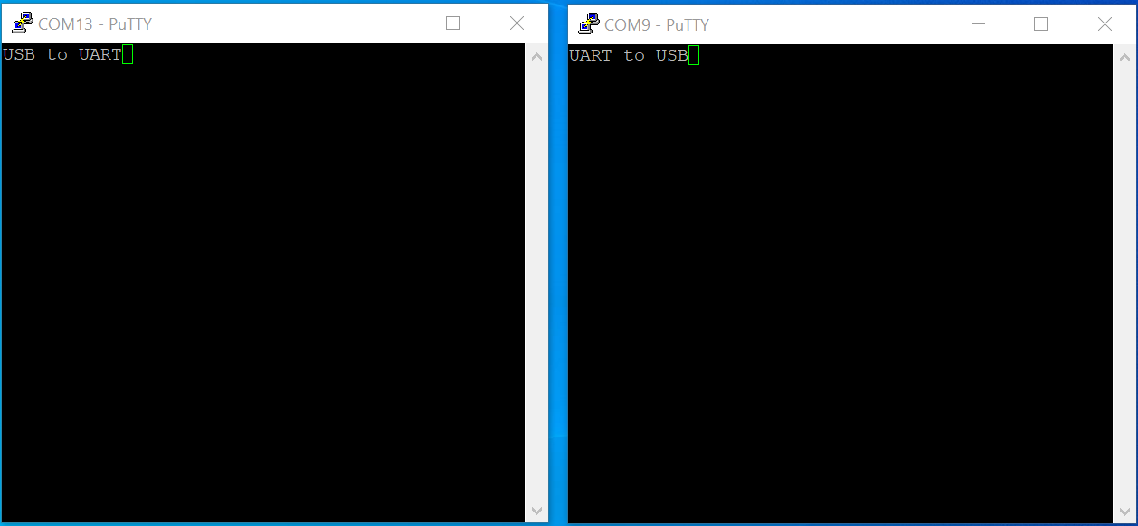
If running the code in stand alone mode, PC terminals programs will need to be opened (for example PuTTy, TeraTerm or simliar terminal applications). An example of the stand alone is shown in Figure 1-3. Typing on the USB terminal will display the data on the UART terminal and vice versa.
 Figure 1-3 USB to UART Bridge Stand Alone Demo
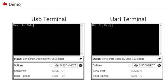
For the GUI demo, the GUI is used as a dual-terminal display and shown in Figure 1-4. The GUI has the terminals labeled but does not prevent the user from changing the COM ports. The COM port selector can be used to select the correct COM port. If the correct COM port does not show up, click the refresh arrow (turning arrow). Remember that the USB COM port only shows up when the program is running on the microcontroller. If the baud rate was changed in the program, match the baud rates in the baud rate selector. When the COM port and baud rate are correctly selected, click on the connect button (depicted as a link) to connect the COM ports to the GUI. Type in either terminal the result will then appear on the opposite terminal.
 Figure 1-4 USB to UART Bridge GUI Demo
To Get Started
1. Watch the training video USB-to-UART Bridge with a Housekeeping MCU to learn how to use the GUI to send data across the USB-to-UART bridge.
2. Order a MSP430F5529 LaunchPad kit to evaluate the USB-to-UART Bridge example code and GUI.
3. Download and test the USB-to-UART Bridge example GUI.
4. Evaluate the USB-to-UART Bridge example code for the MSP430F5529 LaunchPad kit.
| Part Number | Key Features |
|---|---|
MSP430F5529 | 128KB Flash, 8KB RAM, 12-bit ADC, UART/SPI/I2C, 5 Timers, USB, Up to 25MHz Clock |