JAJSE26 October 2017 MSP432E411Y
PRODUCTION DATA.
- 1デバイスの概要
- 2改訂履歴
- 3Device Characteristics
- 4Terminal Configuration and Functions
-
5Specifications
- 5.1 Absolute Maximum Ratings
- 5.2 ESD Ratings
- 5.3 Recommended Operating Conditions
- 5.4 Recommended DC Operating Conditions
- 5.5 Recommended GPIO Operating Characteristics
- 5.6 Recommended Fast GPIO Pad Operating Conditions
- 5.7 Recommended Slow GPIO Pad Operating Conditions
- 5.8 GPIO Current Restrictions
- 5.9 I/O Reliability
- 5.10 Current Consumption
- 5.11 Peripheral Current Consumption
- 5.12 LDO Regulator Characteristics
- 5.13 Power Dissipation
- 5.14 Thermal Resistance Characteristics, 212-Pin ZAD (NFBGA) Package
- 5.15
Timing and Switching Characteristics
- 5.15.1 Load Conditions
- 5.15.2 Power Supply Sequencing
- 5.15.3 Reset Timing
- 5.15.4
Clock Specifications
- 5.15.4.1 PLL Specifications
- 5.15.4.2 PIOSC Specifications
- 5.15.4.3 Low-Frequency Oscillator Specifications
- 5.15.4.4 Hibernation Low-Frequency Oscillator Specifications
- 5.15.4.5 Main Oscillator Specifications
- 5.15.4.6 Main Oscillator Specification WIth ADC
- 5.15.4.7 System Clock Characteristics With USB Operation
- 5.15.5 Sleep Modes
- 5.15.6 Hibernation Module
- 5.15.7 Flash Memory
- 5.15.8 EEPROM
- 5.15.9 Input/Output Pin Characteristics
- 5.15.10 External Peripheral Interface (EPI)
- 5.15.11 Analog-to-Digital Converter (ADC)
- 5.15.12 Synchronous Serial Interface (SSI)
- 5.15.13 Inter-Integrated Circuit (I2C) Interface
- 5.15.14 Ethernet Controller
- 5.15.15 Universal Serial Bus (USB) Controller
- 5.15.16 LCD Controller
- 5.15.17 Analog Comparator
- 5.15.18 Pulse-Width Modulator (PWM)
- 5.15.19 Emulation and Debug
-
6Detailed Description
- 6.1 Overview
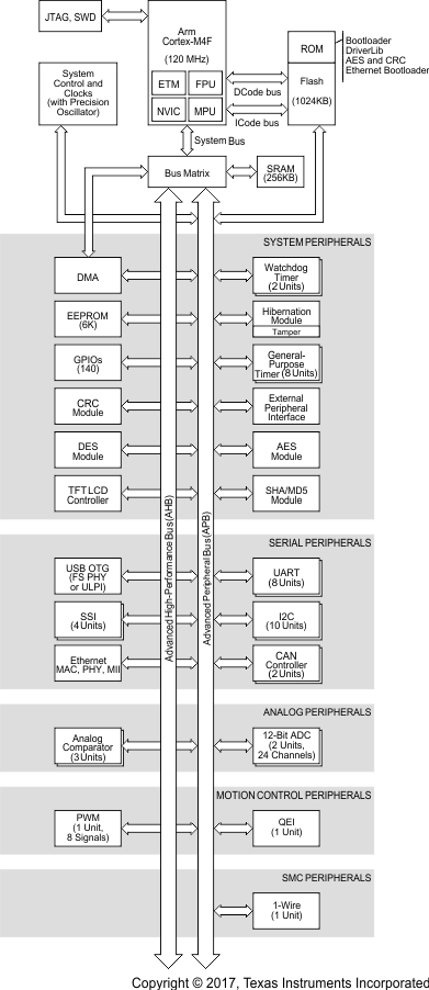
- 6.2 Functional Block Diagram
- 6.3 Arm Cortex-M4F Processor Core
- 6.4 On-Chip Memory
- 6.5
Peripherals
- 6.5.1 External Peripheral Interface (EPI)
- 6.5.2 Cyclical Redundancy Check (CRC)
- 6.5.3 Advanced Encryption Standard (AES) Accelerator
- 6.5.4 Data Encryption Standard (DES) Accelerator
- 6.5.5 Secure Hash Algorithm/Message Digest Algorithm (SHA/MD5) Accelerator
- 6.5.6 Serial Communications Peripherals
- 6.5.7 System Integration
- 6.5.8 LCD Controller
- 6.5.9 Advanced Motion Control
- 6.5.10 Analog
- 6.5.11 JTAG and Arm Serial Wire Debug
- 6.5.12 Peripheral Memory Map
- 6.6 Identification
- 6.7 Boot Modes
- 7Applications, Implementation, and Layout
- 8デバイスおよびドキュメントのサポート
- 9メカニカル、パッケージ、および注文情報
1 デバイスの概要
1.1 特長
-
コア
- 浮動小数点ユニット(FPU)内蔵の120MHz Arm® Cortex®-M4Fプロセッサコア
-
コネクティビティ
- イーサネットMAC: 10/100イーサネットMAC、MII (Media-Independent Interface)およびRMII (Reduced MII)搭載
- イーサネットPHY: IEEE 1588 PTPハードウェアに対応したPHY
- ユニバーサル・シリアル・バス(USB): USB 2.0 OTG、ホスト、またはデバイスと、ULPIインターフェイス・オプションおよびリンク電力管理(LPM)
- 8つのユニバーサル非同期レシーバ/トランスミッタ(UART)、それぞれに独立クロックのトランスミッタおよびレシーバを搭載
- バイSSI、クワッドSSI、アドバンストSSI対応の、4つのクワッド同期シリアル・インターフェイス(QSSI)モジュール
- 高速モード対応の、10個のI2C (Inter-Integrated Circuit)モジュール
- 2つのCAN 2.0AおよびBコントローラ: マルチキャスト共有シリアルバス標準
- 1つの1線式モジュール: 双方向シリアル通信プロトコルにより、単一のワイヤで電力とデータの両方を転送
-
メモリ
- 4バンク構成の1024KBのフラッシュ・メモリにより、各バンクで独立したコード保護に対応
- シングル・サイクル・アクセスの256KBのSRAMにより、120MHzのクロック周波数で2GB/sに近いメモリ帯域幅を実現
- 6KBのEEPROM: 2ページ・ブロックごとに500k書き込み、レベリング、ロック保護
- 内部ROM: SimpleLink™SDKソフトウェアがロード済み
- ペリフェラル・ドライバ・ライブラリ
- ブートローダー
- 外部ペリフェラル・インターフェイス(EPI): 8、16、32ビットの専用パラレル・インターフェイスにより、外部のデバイスおよびメモリ(SDRAM、フラッシュ、またはSRAM)にアクセス
-
セキュリティ
- AES (Advanced Encryption Standard): 128、192、256ビットのキーによる、ハードウェア・アクセラレーション付きのデータの暗号化および復号
- DES (Data Encryption Standard): キー有効長168ビットのブロック暗号実装により、ハードウェア・アクセラレーション付きのデータの暗号化および復号に対応
- SHA/MD5 (Secure Hash Algorithm/Message Digest Algorithm): SHA-1、SHA-2、MD5ハッシュ計算に対応する高度なハッシュ・エンジン
- 巡回冗長性検査(CRC)ハードウェア
- タンパ: 4つのタンパ入力と、設定可能なタンパ事象応答をサポート
-
アナログ
- 2つの12ビットのSARベースADCモジュール、それぞれが最大で毎秒200万サンプル(2Msps)をサポート
- 3つの独立したアナログ・コンパレータ・コントローラ
- 16個のデジタル・コンパレータ
-
システム管理
- JTAGおよびシリアル・ワイヤ・デバッグ(SWD): Arm SWDが内蔵された1つのJTAGモジュールにより、テスト用デザインへのアクセスおよび制御機能、たとえばI/Oピンの観察と制御、スキャン・テスト、デバッグなどが可能
-
開発キットとソフトウェア(ツールとソフトウェアを参照)
- SimpleLink™MSP-EXP432E401Y LaunchPad™開発キット
- SimpleLink MSP432E4ソフトウェア開発キット(SDK)
-
パッケージ情報
- パッケージ: 212ボールのNFBGA (ZAD)
- 拡張動作温度範囲(周囲): -40℃~105℃
1.2 アプリケーション
- 産業用イーサネット・ ゲートウェイ
- 産業用スマート・ゲートウェイ
- ビルディング・オートメーション用ゾーン・コントローラ
- ファクトリ・オートメーション用のデータ・コレクタおよびゲートウェイ
- 電力網インフラストラクチャ用のデータ・コンセントレータ
- ワイヤレスからイーサネットへのゲートウェイ
1.3 概要
SimpleLink MSP432E411YArm® Cortex®-M4Fマイクロコントローラは、最高の性能と高度な統合を実現しています。この製品ファミリは、強力な制御処理とコネクティビティ機能が必要で、優れたコスト効率を求められるようなアプリケーションを対象としています。
MSP432E411Yマイクロコントローラには、各種の豊富な通信機能が組み込まれており、性能と消費電力との間でクリティカルなリアルタイム制御が可能なため、従来とは一線を画す、新しい高度に接続された設計が可能になります。このマイクロコントローラは、通信ペリフェラルや、他の高性能アナログおよびデジタル機能を内蔵しており、ヒューマン・マシン・インターフェイス(HMI)からネットワークに接続したシステム管理コントローラまで、さまざまな対象に使用できる強固な基盤となります。
さらに、MSP432E411Yマイクロコントローラには、広範な開発ツール、システム・オン・チップ(SoC)インフラストラクチャ、Armベースのマイクロコントローラの大規模なユーザー・コミュニティなどの利点があります。また、これらのマイクロコントローラはArm Thumb®互換の Thumb-2®命令セットを使用して、メモリ要件、結果的にコストを削減しています。SimpleLink MSP432™SDKを使用するとき、MSP432E411Yマイクロコントローラは大規模なSimpleLinkファミリのすべてのメンバとコード互換なため、要求に対して正確かつ柔軟に対応できます。
MSP432E411Yデバイスは、SimpleLinkマイクロコントローラ(MCU)プラットフォームの一部です。このプラットフォームは、 Wi-Fi®、 Bluetooth®Low Energy、サブ1GHz、イーサネット、Zigbee、Thread、ホストMCUで構成されており、これらはすべて共通の、単一のコア・ソフトウェア開発キット(SDK)と豊富なツールセットを含む、使いやすい開発環境を共有します。SimpleLinkプラットフォームは一回で統合を実現できるため、製品ラインアップに属する任意のデバイスの組み合わせを実際の設計に追加でき、設計要件が変化した場合でも100%のコード再利用が可能です。詳細については、www.tij.co.jp/simplelinkをご覧ください。
